Capacitive sensor

A capacitive sensor and cable technology, which is applied in the field of sensors, can solve the problems of high cost, sudden change in capacitance value, and high process difficulty, and achieve the effects of ensuring high temperature resistance, convenient online monitoring, and reducing manufacturing costs

Inactive Publication Date: 2014-03-26
ZHEJIANG ZHONGXIN POWER MEASUREMENT & CONTROL TECH
View PDF6 Cites 9 Cited by
  • Summary
  • Abstract
  • Description
  • Claims
  • Application Information

AI Technical Summary

Problems solved by technology

[0003] At present, in a capacitive sensor, the surface of the ceramic insulating ring is metallized, and then it is fixedly connected to the metal jacket by brazing, which has the following disadvantages: First, the metallization of the ceramic insulating ring surface is not only expensive , and the process is difficult, and the surface of the ceramic cannot be evenly metallized, which affects the quality of the brazing, so that good air tightness cannot be guaranteed; second, the ceramic insulating ring can only use 95 ceramics that can be metallized on the surface, However, the capacitance value of 95 ceramics will change suddenly at 400-600°C, and the electrical insulation performance cannot be satisfied at high temperatures, so this kind of capacitance sensor cannot work in high temperature environments.

Method used


Image

  • Capacitive sensor
  • Capacitive sensor
  • Capacitive sensor

Examples


Embodiment 1

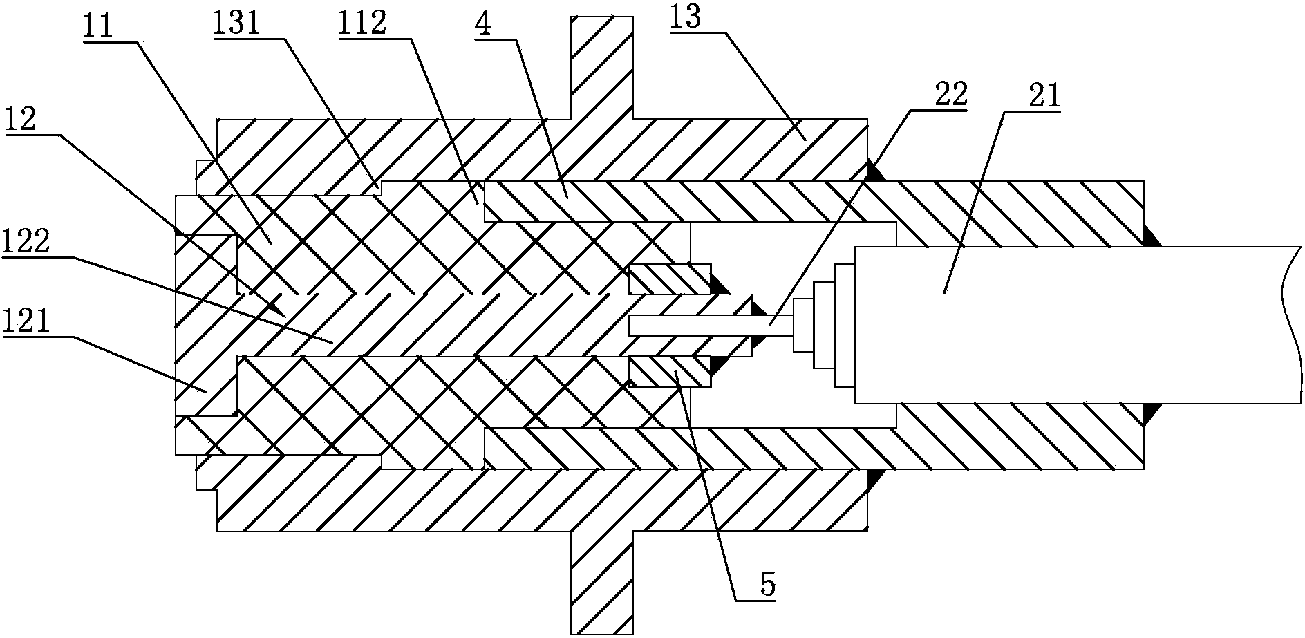
[0016] Embodiment 1: a capacitance sensor, including a high temperature probe, a high temperature hard cable and a low temperature flexible cable, such as figure 1 As shown, the high-temperature probe includes a ceramic insulating ring 11 using 99 alumina ceramics and a core pole 12 and a metal jacket 13 of Kovar alloy with the closest thermal expansion coefficient to 99 alumina ceramics. On the ring wall of the ceramic insulating ring 11 The wall thickness D at the thinnest part is D=0.2mm. The core pole 12 includes a clamping ring 121 and a connecting rod 122. One end of the ceramic insulating ring 11 is provided with a clamping cavity matching the clamping ring 121. The high temperature hard cable It includes a metal outer shielding layer 21 and a high-temperature core wire 22, the high-temperature core wire 22 is fixedly connected to the connecting rod 122 by laser welding, the outer wall of the ceramic insulating ring 11 is provided with a positioning convex ring 112 protr...

Embodiment 2

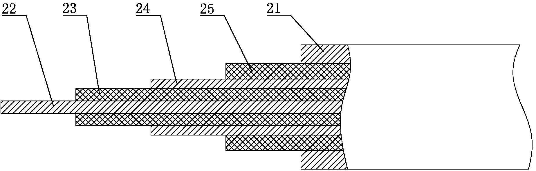
[0019] Embodiment 2: The remaining parts are the same as Embodiment 1, except that the value of the outer diameter of the high-temperature core wire 22 is 0.6 mm, the value of the wall thickness of the high-temperature inner insulating layer 23 is 0.4 mm, and the value of the high-temperature inner shielding layer 24 is 0.6 mm. The value of the layer wall thickness is 0.3 mm, the value of the layer wall thickness of the high-temperature outer insulating layer 25 is 1.1 mm, and the value of the layer wall thickness of the metal outer shielding layer 21 is 0.32 mm.

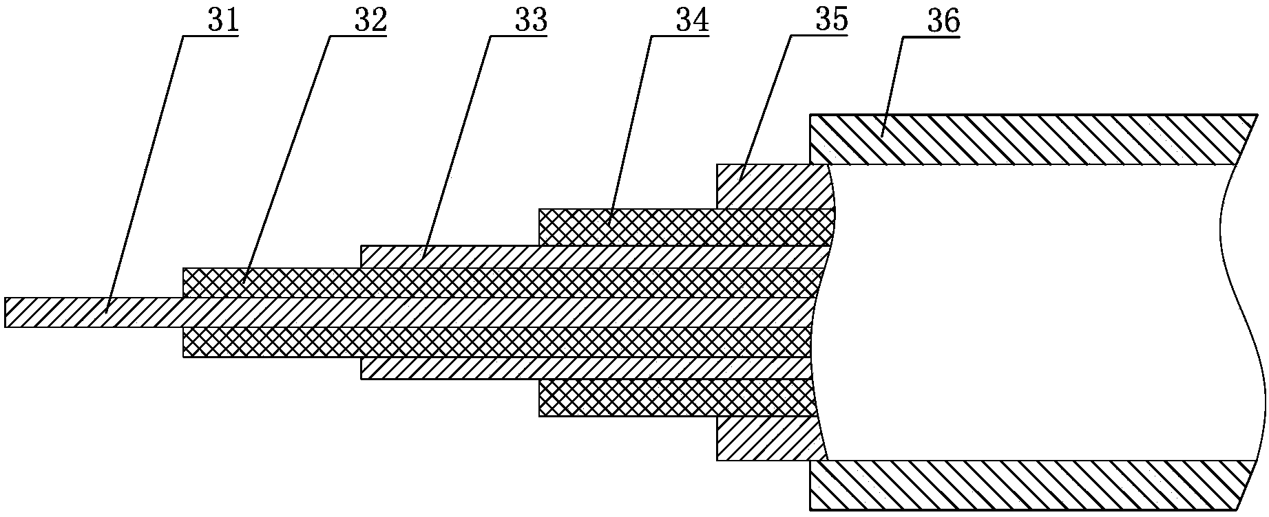
[0020] The value of the outer diameter of the low-temperature core wire 31 is 0.3 mm, the value of the wall thickness of the low-temperature inner insulating layer 32 is 0.4 mm, the value of the wall thickness of the low-temperature inner shielding layer 33 is 0.4 mm, and the value of the layer wall thickness of the low-temperature outer insulating layer 34 is 0.4 mm. The wall thickness has a value of 1.5 mm, and the...

Embodiment 3

[0021] Embodiment 3: the rest is the same as Embodiment 1, the difference is that the value of the outer diameter of the high temperature core wire 22 is 0.4 mm, the value of the wall thickness of the high temperature inner insulating layer 23 is 0.3 mm, and the value of the high temperature inner shielding layer 24 is 0.4 mm. The value of the layer wall thickness is 0.25 mm, the value of the layer wall thickness of the high temperature outer insulating layer 25 is 0.8 mm, and the value of the layer wall thickness of the metal outer shielding layer 21 is 0.26 mm.

[0022]The value of the outer diameter of the low-temperature core wire 31 is 0.25 mm, the value of the wall thickness of the low-temperature inner insulating layer 32 is 0.3 mm, the value of the layer wall thickness of the low-temperature inner shielding layer 33 is 0.3 mm, and the value of the layer wall thickness of the low-temperature outer insulating layer 34 is 0.3 mm. The wall thickness has a value of 1 mm, and...


PUM

PropertyMeasurementUnit
thicknessaaaaaaaaaa

Abstract

The invention discloses a capacitive sensor which is characterized in that a positioning convex ring is arranged on a ceramic insulation ring, the inner wall of a metal jacket is provided with a limiting convex ring, a high-temperature hard cable is connected with the ceramic insulation ring, a core electrode comprises a clamping ring and a connecting rod, one end of the ceramic insulation ring is provided with a clamping cavity, a high-temperature core wire in the high-temperature hard cable is fixedly connected with the connecting rod, a metal pressing sleeve is welded and fixed to a metal outer shielding layer of the high-temperature hard cable, the metal pressing sleeve is connected to the positioning convex ring in a butting mode, and the outer surface of the metal pressing sleeve is fixedly connected with the metal jacket. The capacitive sensor has the advantages that the ceramic insulation ring is fixedly clamped into the metal jacket, surface metallization is needless, a high-temperature probe is firmly connected with the hard-temperature hard cable, the situation that parts fall and a to-be-tested system is damaged can be prevented, welding is carried out between metal, and laser welding can be carried out; due to the fact that the high-temperature hard cable is matched with a low-temperature soft cable, the high-temperature-resistance characteristic can be guaranteed, cost is reduced, and on-line monitoring of the equipment is facilitated.

Description

technical field [0001] The invention relates to a sensor, especially a capacitance sensor. Background technique [0002] The high temperature capacitive sensor is a sensor used in the on-line measurement of the tip clearance of the aeroengine. Therefore, the capacitive sensor should have high sensitivity, high accuracy, air tightness, strong anti-interference and high temperature resistance (capacity 1200°C). [0003] At present, there is a capacitive sensor that metallizes the surface of the ceramic insulating ring, and then uses a brazing process to fix it with the metal jacket. It has the following shortcomings: First, metallizing the surface of the ceramic insulating ring is not only expensive , and the process is difficult, and the surface of the ceramic cannot be evenly metallized, which affects the quality of the brazing, so that good air tightness cannot be guaranteed; second, the ceramic insulating ring can only use 95 ceramics that can be metallized on the surface,...

Claims


Application Information

Patent Timeline
Patent Type & Authority Applications(China)
IPC IPC(8): G01B7/14
Inventor 蒋伟平程晓炜叶德超金鑫杰李辉史训兵
Owner ZHEJIANG ZHONGXIN POWER MEASUREMENT & CONTROL TECH
Why Eureka
Try Eureka