
Leak rate detection apparatus and method for connection position of pressure control system and spacecraft sealed compartment

A detection device and a technology of a sealed cabin, which is applied in the direction of liquid tightness measurement using liquid/vacuum degree, and by measuring the increase and decrease rate of the fluid, etc., can solve the problems of increasing test costs, leak rate detection at joints, and development progress of spacecraft products impact and other issues, to achieve the effect of ensuring development progress, ensuring reliability, and avoiding test interruption

Inactive Publication Date: 2014-03-26
BEIJING INST OF SPACECRAFT ENVIRONMENT ENG
View PDF5 Cites 18 Cited by
  • Summary
  • Abstract
  • Description
  • Claims
  • Application Information

AI Technical Summary

Problems solved by technology

In the preparatory stage of the test, the separate leak rate detection work of the spacecraft airtight cabin and the pressure simulation control system pipeline was completed. Before the test started, the pressure simulation control system pipeline was connected with the spacecraft airtight cabin. The cabin cannot withstand external pressure and because the instruments and equipment in the cabin cannot withstand positive pressure, therefore, it is impossible to use the sealed cabin to evacuate or pressurize the leak rate detection of the connection. At present, it can only rely on the actual experience of the installers and technicians To judge whether the leak rate meets the test requirements, there are certain hidden dangers left. Once the leak rate at the joint cannot meet the requirements, the spacecraft vacuum thermal test will not be able to continue, which not only increases the cost of the test, but also affects the development of spacecraft products. The schedule is affected, so leak rate testing of the connection is necessary

Method used


Image

  • Leak rate detection apparatus and method for connection position of pressure control system and spacecraft sealed compartment
  • Leak rate detection apparatus and method for connection position of pressure control system and spacecraft sealed compartment
  • Leak rate detection apparatus and method for connection position of pressure control system and spacecraft sealed compartment

Examples


Embodiment Construction

[0041] The specific embodiments of the present invention are described in detail below: the specific embodiments of the present invention are implemented on the premise of the technical solutions of the present invention, and detailed embodiments and specific operation procedures are given, but the protection scope of the present invention is not limited to The following examples.

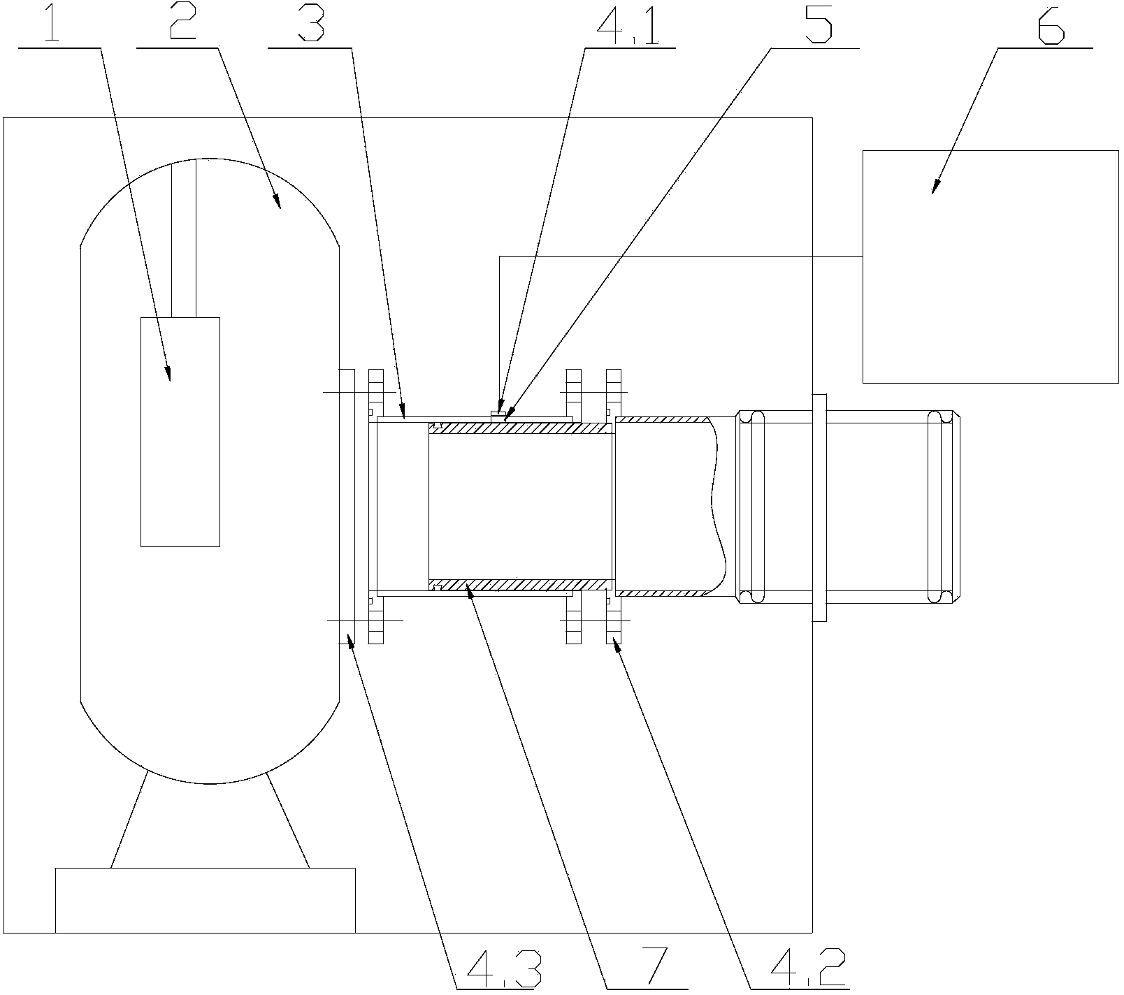
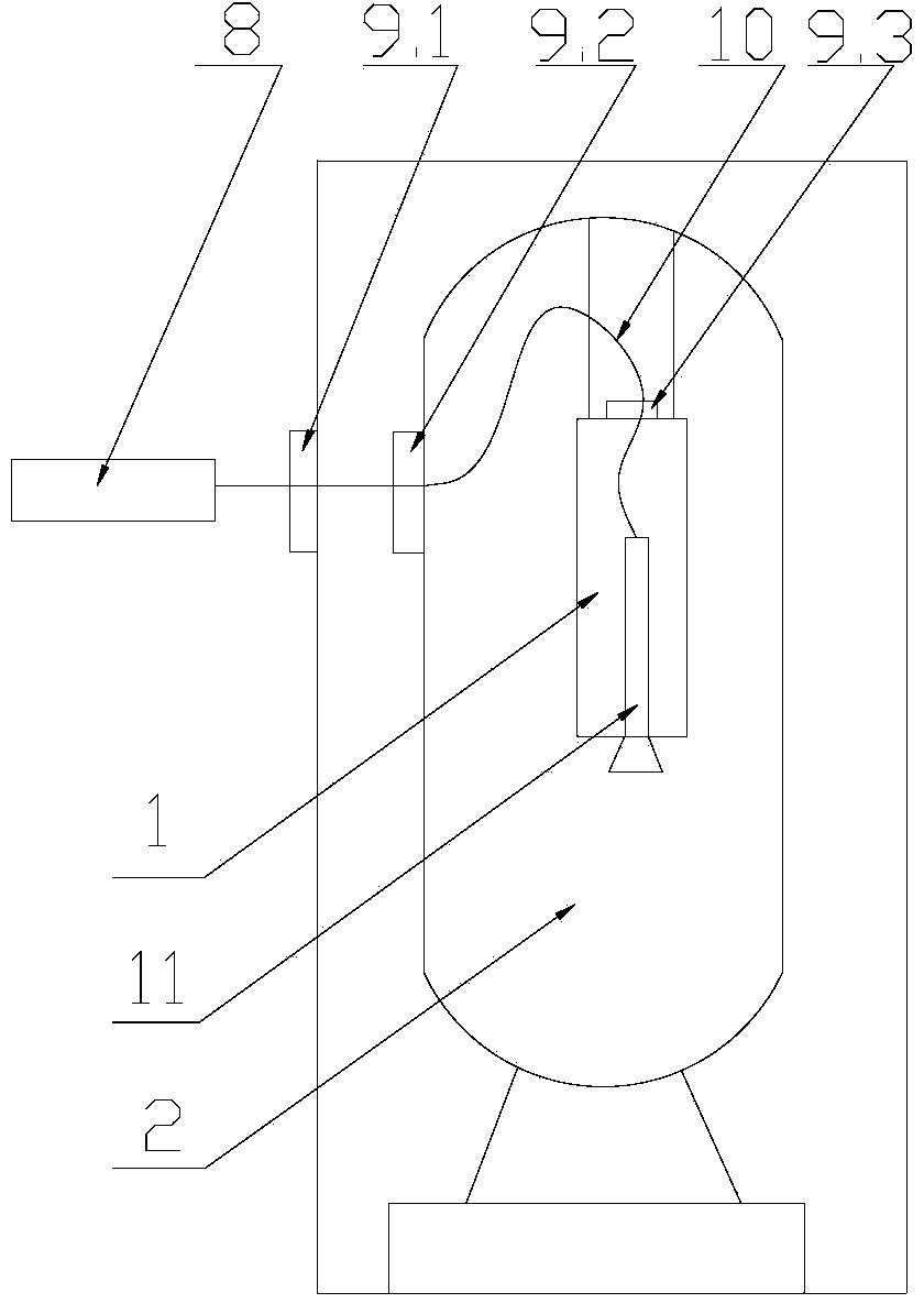
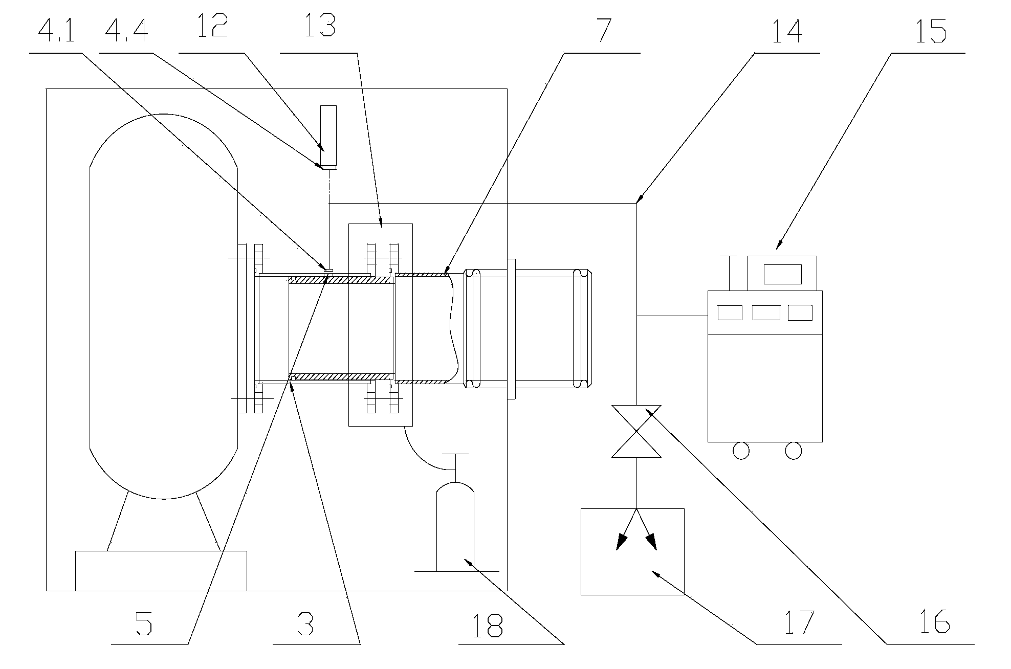
[0042] Such as figure 1 As shown, the pressure simulation control system for vacuum thermal test of the present invention and the leak rate detection device at the junction of the spacecraft airtight cabin include a high-precision vacuum measurement device ( figure 2 (Shown), spacecraft airtight cabin 2, leak rate detection tool 3, helium mass spectrometry leak detection system 6, pressure simulation control system pipeline 7, among which the leak rate detection tool 3 passes the leak detection flange 4.1, the butt flange 4.2, The adapter flange 4.3 is connected with the helium mass spectrometer leak...


PUM


Abstract

The invention discloses a leak rate detection apparatus and method for the connection position of a pressure control system and a spacecraft sealed compartment, for vacuum thermal testing. The apparatus comprises a leak rate detection tool, a high-precision vacuum measuring device, the spacecraft sealed compartment, a pressure simulation control system pipeline and a helium mass spectrum leak detection system, wherein the helium mass spectrum leak detection system comprises an auxiliary suction pump, a helium mass spectrum leak detector, a vacuum standard leakage hole, a pipeline, a valve and the like; the high-precision vacuum measuring device comprises a vacuometer, an electric connector, a communication cable, a vacuum gauge and an auxiliary container; the leak rate detection tool is respectively connected with the spacecraft sealed compartment, the pressure simulation control system pipeline and the helium mass spectrum leak detection system through a flange; and the auxiliary container in the high-precision vacuum measuring device is installed in the spacecraft sealed compartment.

Description

Technical field [0001] The invention belongs to the technical field of non-destructive testing of components of a spacecraft, and specifically relates to a leak rate detection device and a detection method at the connection between a pressure simulation control system for a vacuum thermal test and a sealed cabin of the spacecraft. Background technique [0002] Due to the influence of natural convection caused by gravity, there is a certain deviation between the ground flow and heat transfer test of spacecraft under normal gravity conditions on the ground and the actual situation of spacecraft space. In order to more accurately simulate the flow and heat transfer of the spacecraft vacuum thermal test under the microgravity conditions in space, the pressure reduction method is usually used to suppress the thermal effect of natural convection during the ground test. The lower the pressure in the cabin, the greater the influence of natural convection. When the pressure in the cabin i...

Claims


Application Information

Patent Timeline
Patent Type & Authority Applications(China)
IPC IPC(8): G01M3/28
Inventor 武越许忠旭裴一飞杜春林郭子寅马永来孙娟
Owner BEIJING INST OF SPACECRAFT ENVIRONMENT ENG
Learn More