
Testing device and method for thermal conductivity coefficient of material

A thermal conductivity and testing device technology, which is applied in the field of material thermal conductivity testing devices, can solve the problems of difficulty in ensuring the accuracy of material thermal conductivity testing, difficulty in temperature consistency between the upper and lower sides of the protective plate, and the large thickness range of the test piece. Edge heat loss, shorten the detection cycle, avoid the effect of easy drift

Inactive Publication Date: 2014-03-26
北京中建建筑科学研究院有限公司 +2
View PDF5 Cites 26 Cited by
  • Summary
  • Abstract
  • Description
  • Claims
  • Application Information

AI Technical Summary

Problems solved by technology

However, in the actual test, due to the vertical placement of the sample, the internal temperature field is unevenly distributed, and the temperature consistency between the upper and lower sides of the protective plate is difficult to control. In particular, the small size of the protective plate makes it difficult to test thick specimens due to edge heat loss, and the heat flow meter method is prone to drift, etc. Due to the limitation, it is difficult to guarantee the accuracy of the thermal conductivity test of the material, and it is very restrictive to the thickness range of the test piece
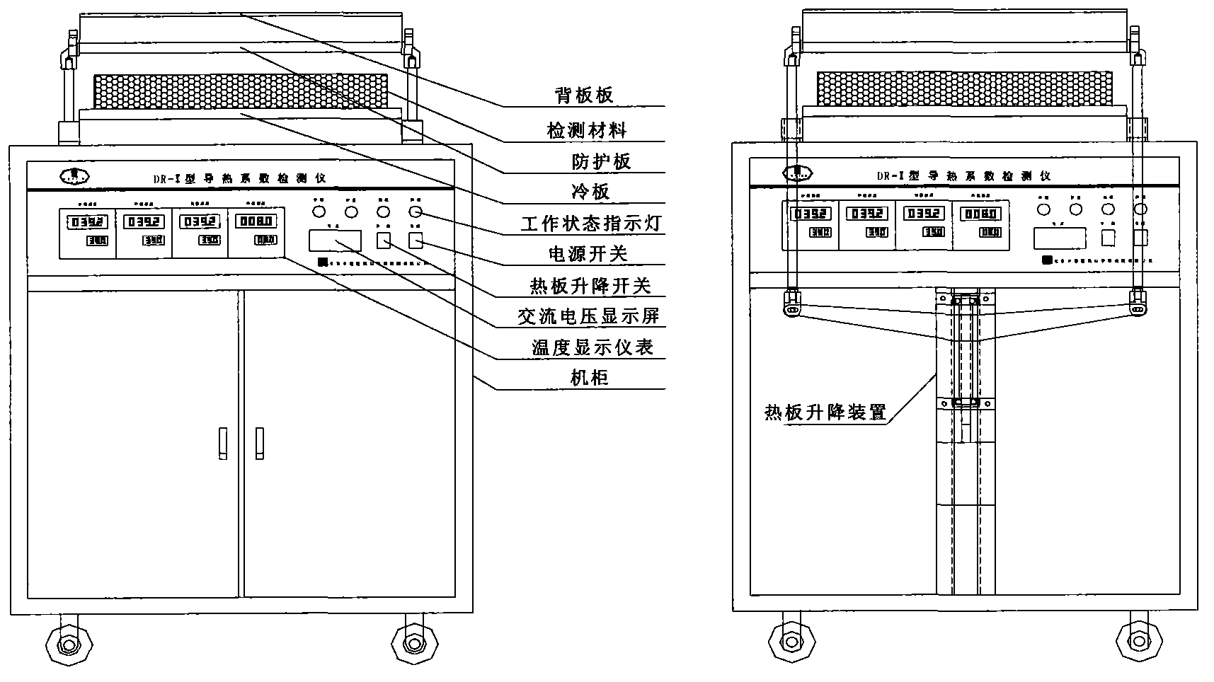
After investigation, there is currently no hot plate (including core plate, guard plate and back plate) and cold plate placed horizontally, the size of the protective plate is 550mm×550mm, the size of the measurement core plate is 300mm×300mm, and the heat flow measurement method is pulse Signal measurement method, the hot plate adopts a thermal conductivity detector with an electric lifting device

Method used


Image

  • Testing device and method for thermal conductivity coefficient of material
  • Testing device and method for thermal conductivity coefficient of material
  • Testing device and method for thermal conductivity coefficient of material

Examples


Embodiment Construction

[0031] The present invention will be further described in detail below in conjunction with the accompanying drawings and through specific embodiments.

[0032] Such as Figure 1~6 As shown, the present invention is suitable for testing specimen thickness less than 100mm, thermal resistance greater than 0.1m 2 • Thermal conductivity or thermal resistance of flat material in K / W. The thermal conductivity detector includes: hot plate heating system, cold plate cooling system, electric lifting system, heat flow measurement system, electrical control and measurement system and industrial computer software control system.

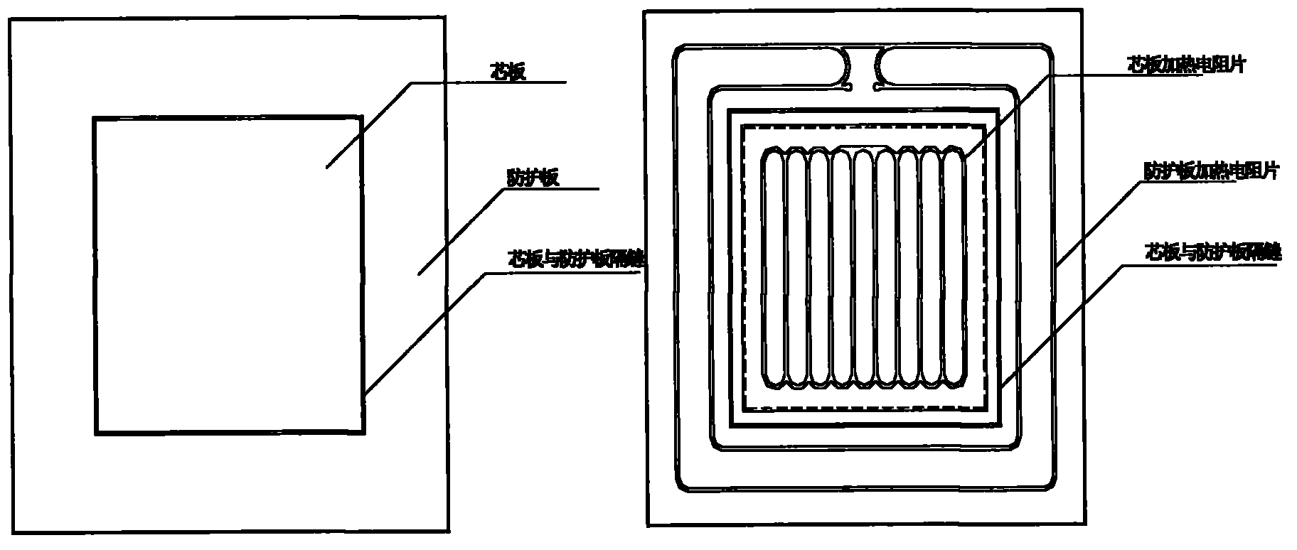
[0033] Hot plate heating systems such as figure 2 As shown, it includes a core board, a protective board and a back board, and each part uses a heating resistance sheet as a heater, and it is a double-heating surface heater, and the material of the heating board panel is aluminum alloy. Among them, the core board is the measurement unit, which is composed of ...


PUM


Abstract

The invention relates to a testing device and a testing method for the thermal conductivity coefficient of a material. The testing device comprises a hot plate heating system, a cold plate cooling system, an electric lifting system, a heat flow metering system, an electrical control and measurement system and an industrial personal computer software control system. The hot plate heating system is horizontally arranged, a core plate, a preventive plate and a back plate of the hot plate heating system respectively comprise a heating resistance sheet and a metal panel, the external dimension of the preventive plate is 550mm*550mm, the electric lifting system comprises a fulcrum bar, a lifting bracket, a lead screw and a driving motor, the lifting fulcrum bar drives a hot plate to lift, and the lifting fulcrum bar and the hot plate can be detached. The testing device for the thermal conductivity coefficient of the material is suitable for testing test pieces with thicknesses less than 100mm, and a building slab type heat-insulating material with the thermal resistance more than 0.1m<2>.K / W, and is high in temperature control precision, short in detection period and accurate in test result, can effectively avoid the influence on the edge hot loss and the drift of a heat-flow meter, and flexible materials are easily tested.

Description

technical field [0001] The invention belongs to the field of material performance detection, and relates to the detection of thermal conductivity or thermal resistance of plate-shaped heat-insulating materials for buildings, in particular to a thermal insulation device formed between a hot plate (including a core plate, a protective plate, and a back plate) and a cold plate. The temperature field simulates the principle of one-dimensional heat transfer, and at the same time, the pulse signal is used to measure the electricity accumulated in the test piece in a short time to calculate the heat flow. The material thermal conductivity test device and method. Background technique [0002] Thermal conductivity is one of the main thermal properties of building materials. Currently, the commonly used test methods are steady-state test methods, including guarded hot plate method and heat flow meter method. From the number of specimens, it can also be divided into double specimen met...

Claims


Application Information

Patent Timeline
IPC IPC(8): G01N25/20
Inventor 赵文海任静吴月华段恺王辰蒋志强
Owner 北京中建建筑科学研究院有限公司
Learn More