
A new type of rotating glasses legs

A spectacle foot, a new technology, applied in the field of glasses, can solve the problems of high production cost, bulky shape and structure, inconvenient assembly, etc., and achieve the effect of convenient operation and use, good rotation effect and good rotation effect

Active Publication Date: 2015-12-30
浙江红润光学有限公司
View PDF8 Cites 0 Cited by
  • Summary
  • Abstract
  • Description
  • Claims
  • Application Information

AI Technical Summary

Problems solved by technology

Ordinary spectacle temples are generally rod-shaped, and there are generally no special decorations or only fixed decorations on the periphery of the temples. The decorations do not change, so it cannot meet the needs of most fashion people.
However, some rotatable spectacle feet in the existing market are restricted by factors such as bulky shape and structure, inconvenient assembly, and high production costs, making it unable to meet greater market demand.

Method used


Image

  • A new type of rotating glasses legs
  • A new type of rotating glasses legs
  • A new type of rotating glasses legs

Examples


Embodiment Construction

[0027] The technical scheme and operation process of the new rotating eyeglass socket of the present invention will be further described below in combination with specific embodiments of the new rotating eyeglass socket of the present invention and the accompanying drawings.

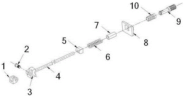
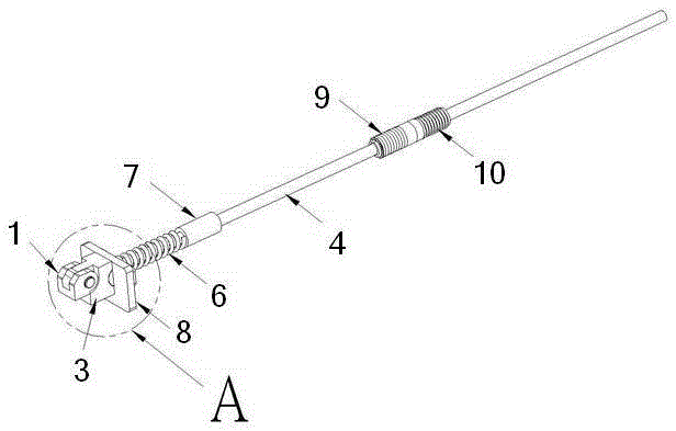
[0028] The structure of a novel rotating spectacle foot of the present invention is as follows: Figure 1 to Figure 5 As shown, it includes a front hinge 1, a hinge screw 2, a rear hinge 3, a rod-shaped foot rod 4, a rotating slider 5, a spring 6, a positioning sleeve 7, a movable trim piece 8, a rotating meson master part 9, The rotating meson sub-part 10 , the rotatable decorative part 11 assembled on the foot bar 4 , and the foot cover 12 . In the present invention, the end close to the front hinge 1 is the front end, and the end close to the rotating meson master part is the tail end or rear end.

[0029] The new rotating spectacle feet of the present invention are connected to the front hinge 1 and...


PUM


Abstract

Disclosed is a rotatable earpiece, comprising a front hinge (1), a rear hinge (3), an earpiece rod (4), a rotatable sliding block (5), a spring (6), a positioning sleeve (7), a pivotable decorative sheet (8) and an earpiece cover (12). The front hinge (1) is movably connected to the front end of the rear hinge (3), the tail end of the rear hinge (3) is fixedly connected to the earpiece rod (4), and the tail part of the rear hinge (3) is provided with a notch. The rotatable sliding block (5) is provided at the notch of the rear hinge (3) by passing through the earpiece rod (4), and the spring (6) butt-joins the tail part of the rotatable sliding block (5) by passing through the earpiece rod (4). The positioning sleeve (7) butt-joins the tail part of the spring (6) by passing through the earpiece rod (4), compresses the spring (6), and then is fixed on the earpiece rod (4). The pivotable decorative sheet (8) is movably nested outside the rotatable sliding block (5), and the rotation thereof can bring the rotatable sliding block (5) together into rotation. The earpiece cover (12) is fixedly wrapped on the outside of the earpiece rod (4), and between the rear hinge (3) and the earpiece cover (12), a rotatable decorative part (11) which can rotate around the earpiece rod (4) is wrapped on the outside of the earpiece rod (4). The tail end of the pivotable decorative sheet (8) is connected to the front end of the rotatable decorative part (11) so that they can rotate in a synchronized manner. This rotatable earpiece is simple in structure, convenient in assembly, low in costs, and easy to rotate and pivot.

Description

technical field [0001] The invention relates to a spectacle socket, in particular to a novel rotating spectacle socket, which belongs to the technical field of glasses. Background technique [0002] Ordinary glasses are generally composed of frames, lenses and temples. Ordinary spectacle temples are generally rod-shaped, and there are generally no special decorations or only fixed decorations on the periphery of the temples. The decorations do not change, so they cannot meet the needs of most fashion people. However, some rotatable spectacle legs in the existing market are restricted by factors such as bulky profile structure, inconvenient assembly, and high production costs, so that they cannot meet the larger market demand. Contents of the invention [0003] Aiming at the above-mentioned problems of the rotatable spectacle temples in the prior art, the present invention provides a new type of swivel spectacle temples with simple structure, convenient assembly, low manuf...

Claims


Application Information

Patent Timeline
Patent Type & Authority Patents(China)
IPC IPC(8): G02C5/16G02C11/02G02C5/22
CPCG02C5/20G02C11/02G02C2200/26G02C2200/30
Inventor 王小艳
Owner 浙江红润光学有限公司
Learn More