Servo synchronous control method and system applied to gantry mechanism

A servo system, synchronous control technology, applied in general control systems, control/regulation systems, adaptive control, etc., can solve problems such as increased equipment cost, increased processing time, and large vibration of the gantry mechanism, to reduce large vibration and improve. The effect of response speed and cost reduction

Active Publication Date: 2017-01-18
成都乐创自动化技术股份有限公司
View PDF5 Cites 0 Cited by
  • Summary
  • Abstract
  • Description
  • Claims
  • Application Information

AI Technical Summary

Problems solved by technology

Since the two servo systems are in the position closed-loop mode, the two servos may work under mutual restraint in order to overcome the stress, which will cause the gantry mechanism to withstand torsion or large vibration during movement
[0005] In the prior art, an external detection device such as a grating scale is used to detect the motion position of the two motors, and the position information is fed back to the upper control system. The upper control system adjusts the motor movement according to the feedback. However, this processing method needs to be added. Install an external detection device, and at the same time, in order to ensure the synchronization of the two motors, the accuracy of the installed detection device is high, which increases the cost of the entire equipment, and increases the cost and difficulty of maintenance. In addition, due to the need for processing by the upper control system, making Increased processing time, not conducive to quick adjustments

Method used


Image

  • Servo synchronous control method and system applied to gantry mechanism
  • Servo synchronous control method and system applied to gantry mechanism

Examples


Embodiment Construction

[0029] An embodiment of the present invention will be further described below in conjunction with the accompanying drawings.

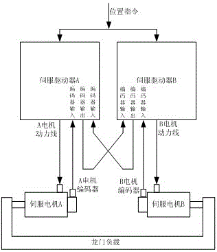
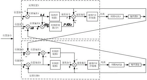
[0030] Servo system applied to gantry mechanism (such as figure 1 ), including servo system A and servo system B, and the drive of the gantry mechanism is completed by two sets of servo systems. The A servo system includes a servo driver A, a servo motor A and a motor encoder A. The servo The system B includes a servo driver B, a servo motor B and a motor encoder B. In the present invention, the position information of the two servo motors is cross-feedback, and the servo driver realizes the synchronous operation function of the two servo motors through a control method of position deviation comparison and correction.

[0031] In order to realize the cross feedback of the position information of two servo motors, the servo driver needs to include at least one encoder signal output interface and at least two encoder signal input interfaces on the hardwa...


PUM


Abstract

The invention provides a servo synchronous control method and system applied to a gantry mechanism. The gantry mechanism is jointly driven by two servo systems, wherein a servo driver of either servo system adjusts a corresponding servo motor controlled by the servo driver by contrasting the positional of the corresponding servo motor controlled by the servo driver with the positional of another servo motor; in this way, synchronization of the two motors is realized. The servo synchronous control method and system applied to the gantry mechanism have the advantages that synchronization compensation of the two motors is realized through the servo systems, synchronization of the two motors is improved, and the problem that the gantry mechanism vibrates sharply and other undesirable problems are reduced; there is no need for using expensive sensors (such as a grating ruler), so that cost and input are reduced, and maintainability is improved; synchronization compensation of the motors is directly realized at the servo systems, processing by an upper computer system is not needed, and the response speed of synchronism compensation is increased.

Description

technical field [0001] The invention relates to the field of motor control, in particular to a multi-motor synchronous control method and system. Background technique [0002] The gantry structure controlled by servo motors is one of the eight core intelligent measurement and control devices and servo control mechanisms in the components described in the "Twelfth Five-Year Development Roadmap for Intelligent Manufacturing Equipment Industry". Due to the mechanical device with gantry structure, often The inertia is large and the load is heavy, so it is difficult to be driven by a driving motor. The more common solution is to install a driving motor on both sides of the gantry device, and the two motors are driven simultaneously during movement. The position commands of the two servo systems are issued by the same host control, that is, the position commands of the two servo systems at the same time are the same. [0003] When the two servo systems on both sides of the gantr...

Claims


Application Information

Patent Timeline
Patent Type & Authority Patents(China)
IPC IPC(8): G05B13/04
Inventor 周旭
Owner 成都乐创自动化技术股份有限公司
Why Eureka
Try Eureka