

Display device and dimming method thereof
A display device, light-emitting diode technology, applied in static indicators, instruments, etc., can solve the problems of reduced pixel aperture ratio, uneven brightness distribution, errors, etc., to improve viewing quality, avoid uneven brightness, reduce or reduce brightness uneven effect
- Summary
- Abstract
- Description
- Claims
- Application Information
AI Technical Summary
Problems solved by technology
Method used
Image

Examples
Embodiment Construction
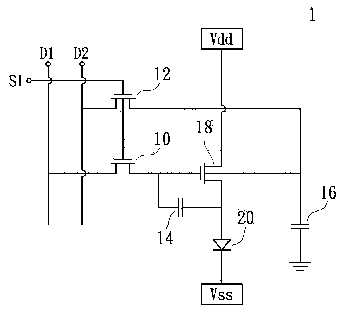
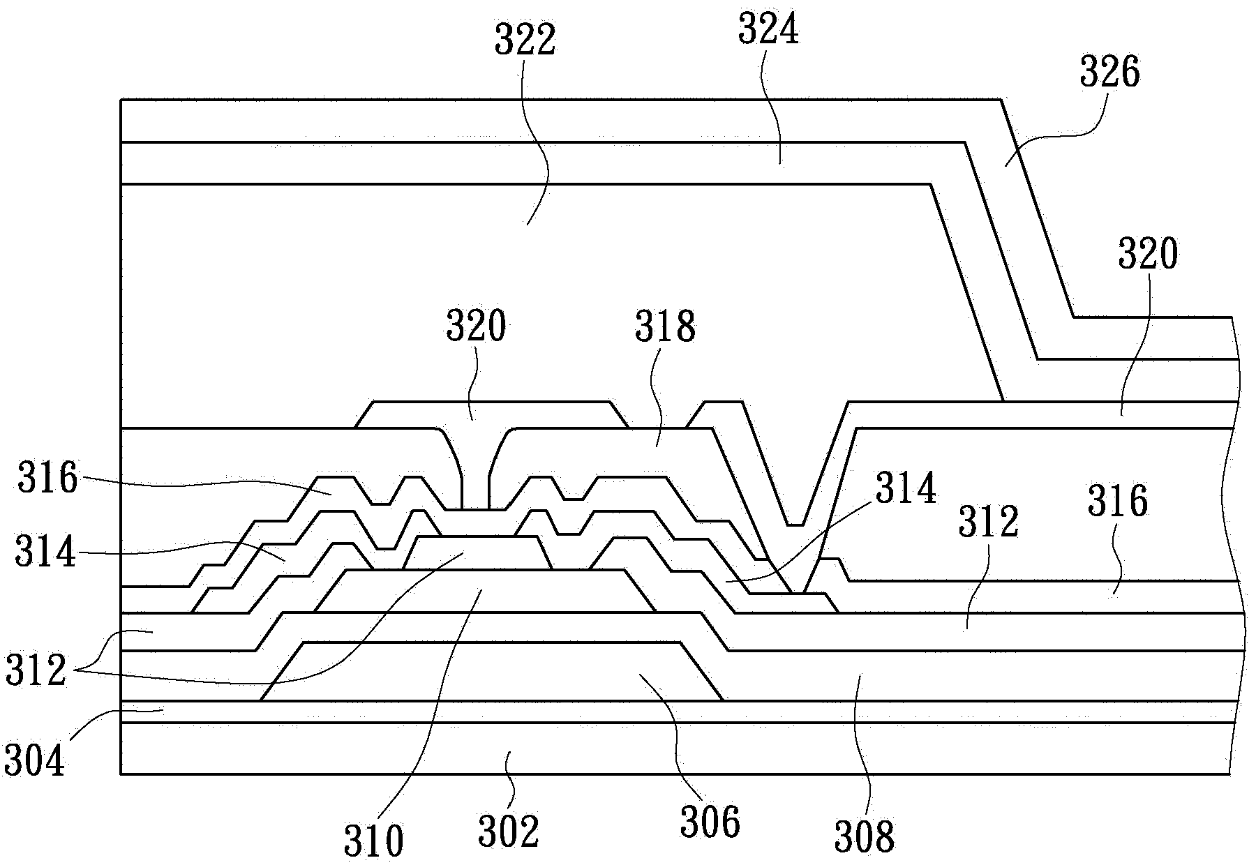
[0047] Please also see Figure 2A and Figure 2B , Figure 2A shows a schematic diagram of a partial circuit of a display device according to an embodiment of the present invention, Figure 2BA partial cross-sectional schematic diagram of a display device according to an embodiment of the present invention is shown. As shown in the figure, the display device 1 has a plurality of pixel groups, and each pixel group has at least a light emitting diode 20 and a driving module (including element symbols 10, 12, 14, 16, 18), so that the driving module can drive the light emitting diode 20 . In detail, the first switch circuit 10 in the drive module is respectively coupled to the gray scale data line D1, the first capacitor 14 and the drive transistor 18, and the second switch circuit 12 is respectively coupled to the compensation data line D2, the second capacitor 16 and the drive transistor 18. Transistor 18. The drive transistor 18 is a four-terminal element, the first gate t...
PUM
 Abstract
Description
Claims
Application Information