Vacuum oil filling and detecting system for transformer

A detection system and technology for transformers, which are used in transformer/inductor cooling, liquid/vacuum measurement for liquid tightness, etc., can solve problems such as unbalanced internal and external pressures of bellows, tensile deformation of bellows, etc., and are easy to popularize. and the effect of circulation

Active Publication Date: 2014-03-26
STATE GRID SHANDONG ELECTRIC POWER
View PDF6 Cites 15 Cited by
  • Summary
  • Abstract
  • Description
  • Claims
  • Application Information

AI Technical Summary

Problems solved by technology

[0006] Therefore, the technical problem to be solved by the present invention is that in the prior art, the vacuuming process easily causes the pressure imbalance inside and outside the bellows, resulting in excessive stretching and deformation of the bellows. Pressure Balanced Transformer Vacuum Oil Filling and Detection System

Method used


Image

  • Vacuum oil filling and detecting system for transformer
  • Vacuum oil filling and detecting system for transformer
  • Vacuum oil filling and detecting system for transformer

Examples


Embodiment 1

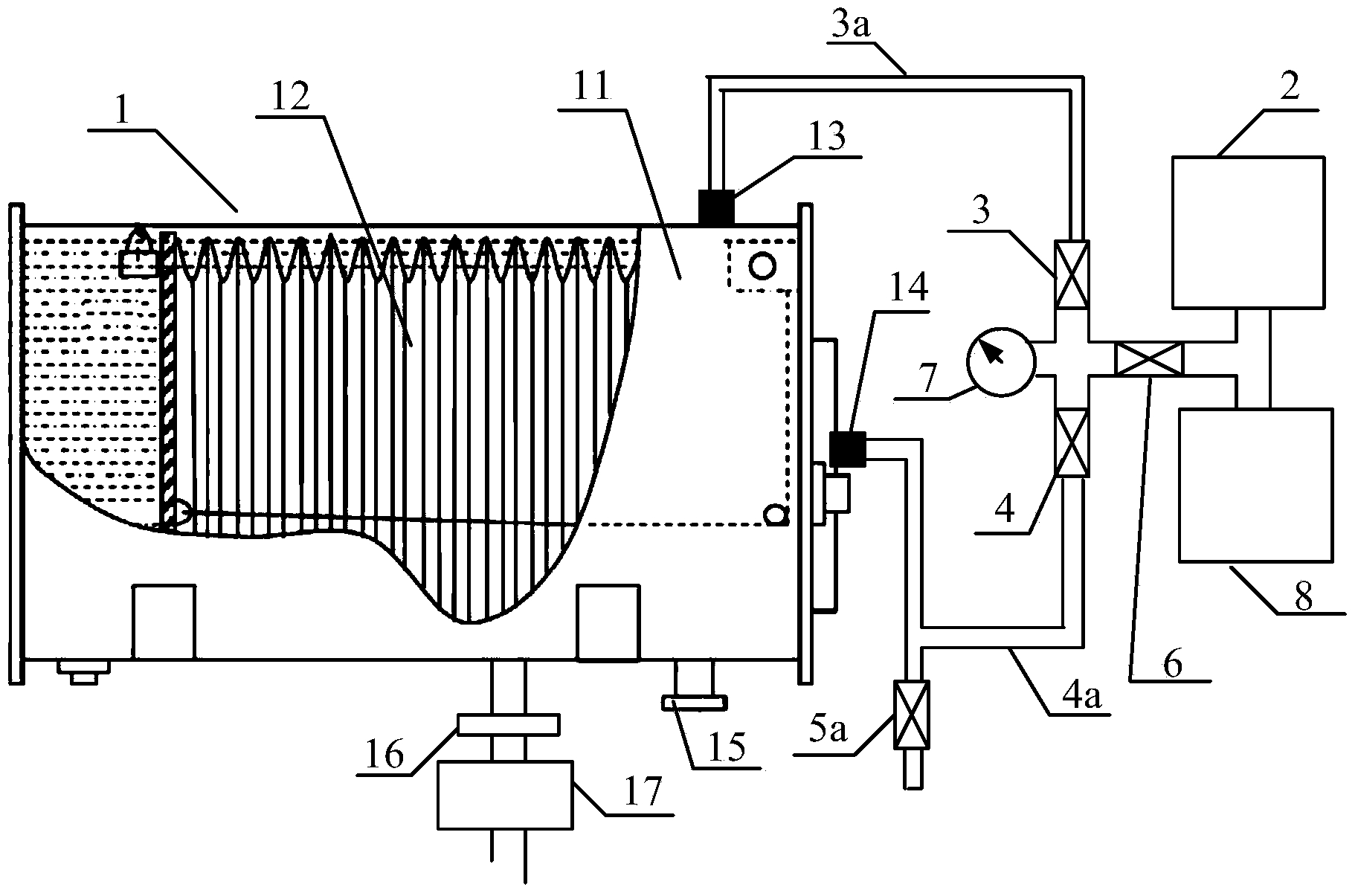
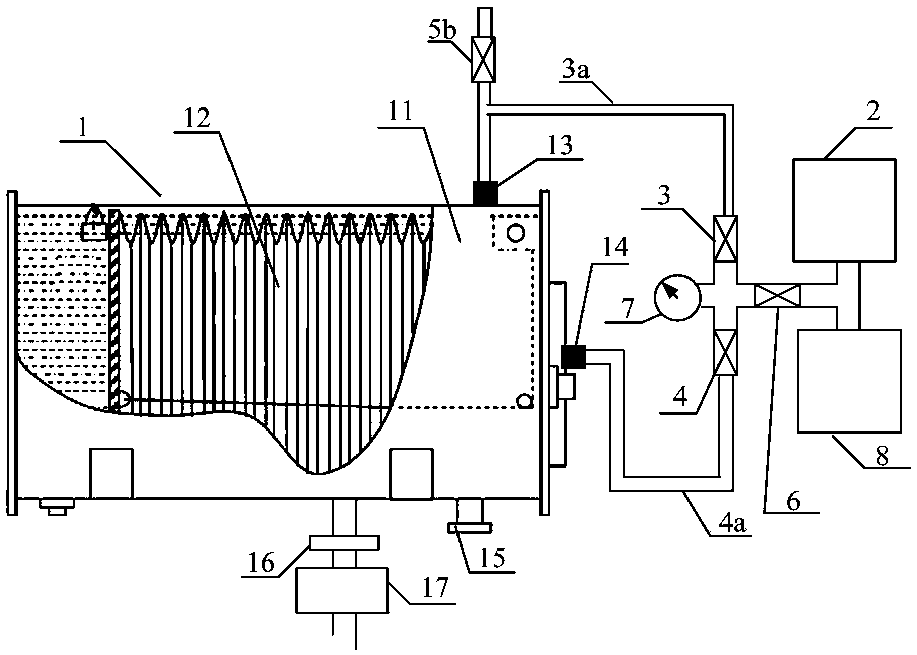
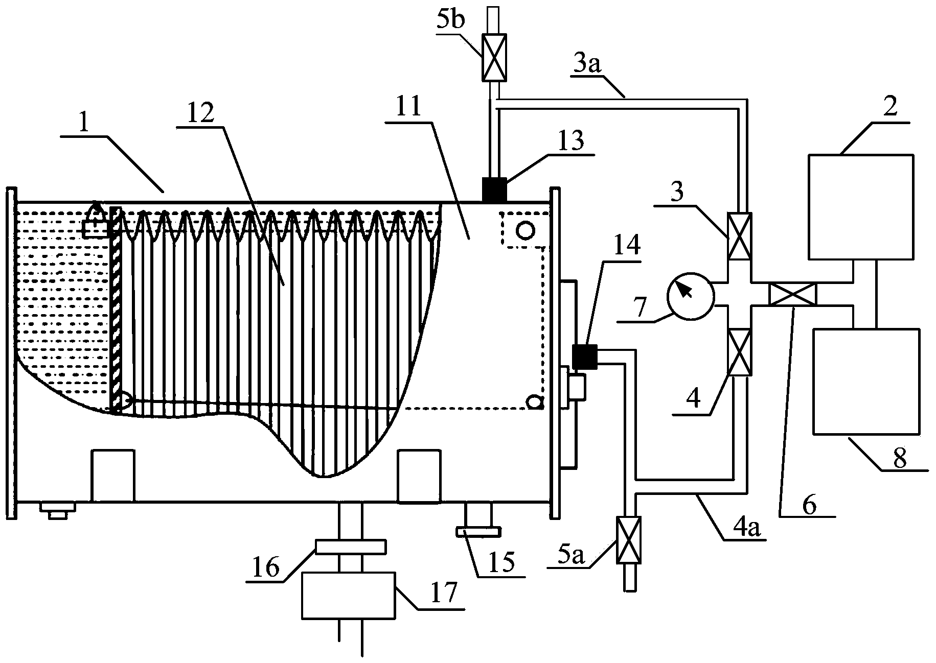
[0042] This embodiment provides a transformer vacuum oil filling and detection system, such as figure 1 , figure 2 , image 3 As shown, it includes a corrugated oil conservator 1 and a vacuum device 2 .

[0043] The chamber between the oil conservator shell 11 and the bellows 12 of the corrugated oil conservator 1 communicates with the exhaust port 13 ; the inner cavity of the bellows 12 communicates with the breathing port 14 .

[0044] The exhaust port 13 is in sealing communication with the vacuum device 2 through the first connecting pipe 3a; the exhaust port vacuum valve 3 is arranged on the first connecting pipe 3a, and the exhaust port vacuum valve 3 control whether the chamber between the oil conservator shell 11 and the bellows 12 communicates with the vacuum device 2 .

[0045] The breathing port 14 is in sealing communication with the vacuum device 2 through the second connecting pipe 4a; the breathing port vacuum valve 4 is arranged on the second connecting pip...

Embodiment 2

[0059] On the basis of Embodiment 1, the transformer vacuum oil filling and detection system described in this embodiment, such as figure 1 , figure 2 , image 3 shown, also includes:

[0060] The main valve 6, one end of which is in sealing communication with the vacuum device 2, and the other end is in sealing communication with the exhaust port vacuum valve 3 and the breathing port vacuum valve 4 respectively, through the opening and closing of the main valve 6 Control whether the exhaust port vacuum valve 3 and the breathing port vacuum valve 4 communicate with the vacuum device 2 .

[0061] By setting the main valve 6, it can work together with the vacuum valve 3 at the exhaust port to prevent the transformer oil from entering the vacuum device 2 from the first connecting pipe 3a during vacuum oil filling, causing damage to the vacuum device 2, and realizing double insurance control .

[0062] As a preferred implementation, the transformer vacuum oiling and detection...

Embodiment 3

[0068] On the basis of Embodiment 1 or Embodiment 2, the transformer vacuum oiling and detection system described in this embodiment, such as figure 1 , figure 2 , image 3 shown, also includes:

[0069] The inflation device 8 is in sealing communication with the main valve 6 .

[0070] The inflation device 8 can be an air pump.

[0071] As an optional implementation mode, in the transformer vacuum oiling and detection system described in this embodiment, the main valve 6, the vacuum device 2 and the inflation device 8 are in sealed communication through a three-way pipe joint.

[0072] When the vacuum oiling operation is finished, close the exhaust port vacuum valve 3, the regulating valve and the vacuum device 2, and open the breathing port vacuum valve 4 and the main valve 6, because the inflation device 8 is sealed with the main valve 6 through the three-way pipe joint Therefore, the inflatable device 8 is opened, and air pressure can be added to the inner cavity of t...


PUM


Abstract

The invention relates to a vacuum oil filling and detecting system for a transformer. The vacuum oil filling and detecting system comprises a corrugated oil conservator and a vacuumizing device; a cavity between an oil conservator shell and a corrugated pipe is communicated with an exhaust port; an inner cavity of the corrugated pipe is communicated with an air port; the exhaust port is communicated with the vacuumizing device through a first connecting pipe in a sealed mode; an exhaust port vacuumizing valve is arranged on a first connecting pipe, and the cavity between the oil conservator shell and the corrugated pipe and the vacuumizing device are controlled to be communicated or not through opening or closing of the exhaust port vacuumizing valve; the air port is communicated with the vacuumizing device in a sealed mode through a second connecting pipe; an air port vacuumizing valve is arranged on the second connecting pipe, and the inner cavity of the corrugated pipe and the vacuumizing device are controlled to be communicated or not through opening or closing of the air port vacuumizing valve; one end of an adjusting valve is connected to the outside of the air port and / or exhaust port, the other end of the adjusting valve is communicated with air, and the air port and / or air exhaust port and the air are controlled to be communicated or not through opening or closing of the adjusting valve.

Description

technical field [0001] The invention relates to a transformer vacuum oil filling and detection system. Specifically, it is a vacuum oil filling and detection system suitable for a transformer with a corrugated oil conservator. Background technique [0002] The oil conservator, commonly known as an oil pillow, is placed horizontally above the transformer oil tank and communicates with the transformer oil tank through a butterfly valve and a gas relay. When the transformer oil is heated and expands, the transformer oil flows from the oil tank to the oil storage tank; when the transformer oil contracts when it is cooled, the transformer oil flows from the oil storage tank to the oil tank. Therefore, by installing an oil conservator, the volume expansion or contraction of the transformer oil due to temperature changes can be compensated, and at the same time, the transformer oil can be isolated from the air, which is an important protection component for the safe operation of t...

Claims


Application Information

Patent Timeline
Patent Type & Authority Applications(China)
IPC IPC(8): H01F27/14G01M3/02
Inventor 胡东郑强张金良张鹏刘宁
Owner STATE GRID SHANDONG ELECTRIC POWER
Why Eureka
Try Eureka