
Electrostatic discharge protection circuit device

A technology for electrostatic discharge protection and circuit devices, which is applied in the field of electrostatic discharge protection circuit devices, and can solve the problems of general products and methods without suitable structures and methods, inconvenience, and affecting internal circuit operations, etc.

Active Publication Date: 2014-03-26
MACRONIX INT CO LTD
View PDF6 Cites 5 Cited by
  • Summary
  • Abstract
  • Description
  • Claims
  • Application Information

AI Technical Summary

Problems solved by technology

However, the holding voltage of the discharge path provided by this architecture is often less than 10.5 volts
Therefore, when the internal circuit is operating, electrical overstress (EOS) events often occur continuously due to the holding voltage being too low, thereby affecting the operation of the internal circuit
[0004] It can be seen that the above-mentioned existing electrostatic discharge protection circuit device obviously still has inconvenience and defects in structure and use, and needs to be further improved urgently.
In order to solve the above-mentioned existing problems, relevant manufacturers have tried their best to find a solution, but no suitable design has been developed for a long time, and general products and methods do not have appropriate structures and methods to solve the above-mentioned problems. This is obviously a problem that relevant industry players are eager to solve

Method used


Image

  • Electrostatic discharge protection circuit device
  • Electrostatic discharge protection circuit device
  • Electrostatic discharge protection circuit device

Examples


Embodiment Construction

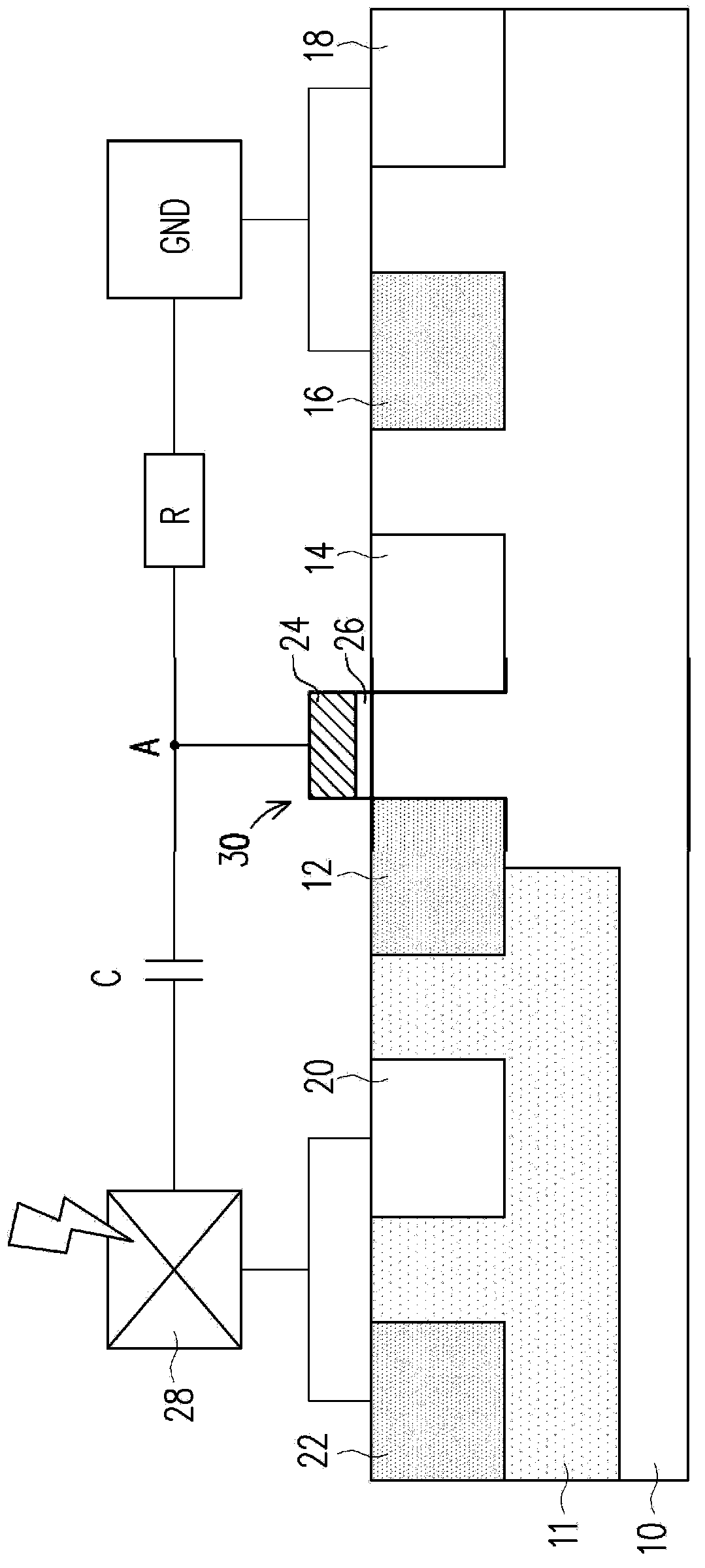
[0048] In order to further explain the technical means and effects of the present invention to achieve the intended purpose of the invention, the specific implementation, structure, steps, and features of the electrostatic discharge protection circuit device proposed according to the present invention will be described below in conjunction with the accompanying drawings and preferred embodiments. And its effect, detailed description is as follows.

[0049] The aforementioned and other technical contents, features and effects of the present invention will be clearly presented in the following detailed description of preferred embodiments with reference to the drawings. Through the description of specific embodiments, it should be possible to obtain a deeper and more specific understanding of the technical means and effects of the present invention to achieve the intended purpose, but the attached drawings are only for reference and description, and are not used to explain the pr...


PUM


Abstract

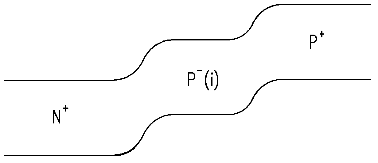
The invention provides an electrostatic discharge protection circuit device. The electrostatic discharge protection circuit device comprises a substrate with a first conduction type, a well zone with a second conduction type and a transistor, wherein the transistor comprises a first doped zone positioned in the substrate, extending to the well zone and provided with the second conduction type, a second doped zone with the first conduction type and a gate electrode positioned at the part, of the substrate, between the first doped zone and the second doped zone. The electrostatic discharge protection circuit device further comprises a third doped zone with the second conduction type and a fourth doped zone with the first conduction type, and the third doped zone and the fourth doped zone are sequentially positioned in the part, of the substrate, on the outer side of the second doped zone with the first conduction type, and are grounded. The electrostatic discharge protection circuit device further comprises a fifth doped zone with the first conduction type and a sixth doped zone with the second conduction type, and the fifth doped zone and the sixth doped zone are sequentially in the part, of the well zone, on the outer side of the first doped zone with the second conduction type, and are connected with a weld pad. When exerted on the weld pad, the electrostatic discharge voltage is coupled with the gate electrode.

Description

technical field [0001] The invention relates to an electrostatic discharge protection circuit device, in particular to an electrostatic discharge protection circuit device with adjustable collapse speed. Background technique [0002] Electrostatic discharge (ESD) is the phenomenon of the movement of static electricity from non-conductive surfaces, which can cause damage to semiconductors and other circuit components in integrated circuits. For example, when a human body walking on a carpet, a machine packaging an integrated circuit or an instrument for testing an integrated circuit touches a chip, it will discharge to the chip. The instantaneous power of this electrostatic discharge may cause damage to the chip. The integrated circuit is damaged or fails. [0003] In order to prevent integrated circuits from being damaged due to electrostatic discharge phenomena, an electrostatic discharge protection circuit device is added to the integrated circuits. Generally speaking, t...

Claims


Application Information

Patent Timeline
Patent Type & Authority Applications(China)
IPC IPC(8): H01L27/02H02H9/04
Inventor 何永涵
Owner MACRONIX INT CO LTD
Learn More