
Semiconductor device

A technology of semiconductor and size packaging, which is applied in the direction of semiconductor devices, circuit devices, semiconductor/solid-state device components, etc., can solve the problems of increased chip cost, increased chip area, chip layout design constraints, etc., and achieve the effect of improving ESD resistance

Inactive Publication Date: 2014-03-26
KK TOSHIBA
View PDF4 Cites 4 Cited by
  • Summary
  • Abstract
  • Description
  • Claims
  • Application Information

AI Technical Summary

Problems solved by technology

[0007] However, the method of increasing the width of the wiring pattern not only imposes great constraints on the layout design of the chip, but also has the problem of increasing the area of ​​the chip and increasing the cost of the chip as a result.

Method used


Image

  • Semiconductor device
  • Semiconductor device
  • Semiconductor device

Examples


Embodiment Construction

[0021] Embodiments will be described below with reference to the drawings.

[0022] (structure)

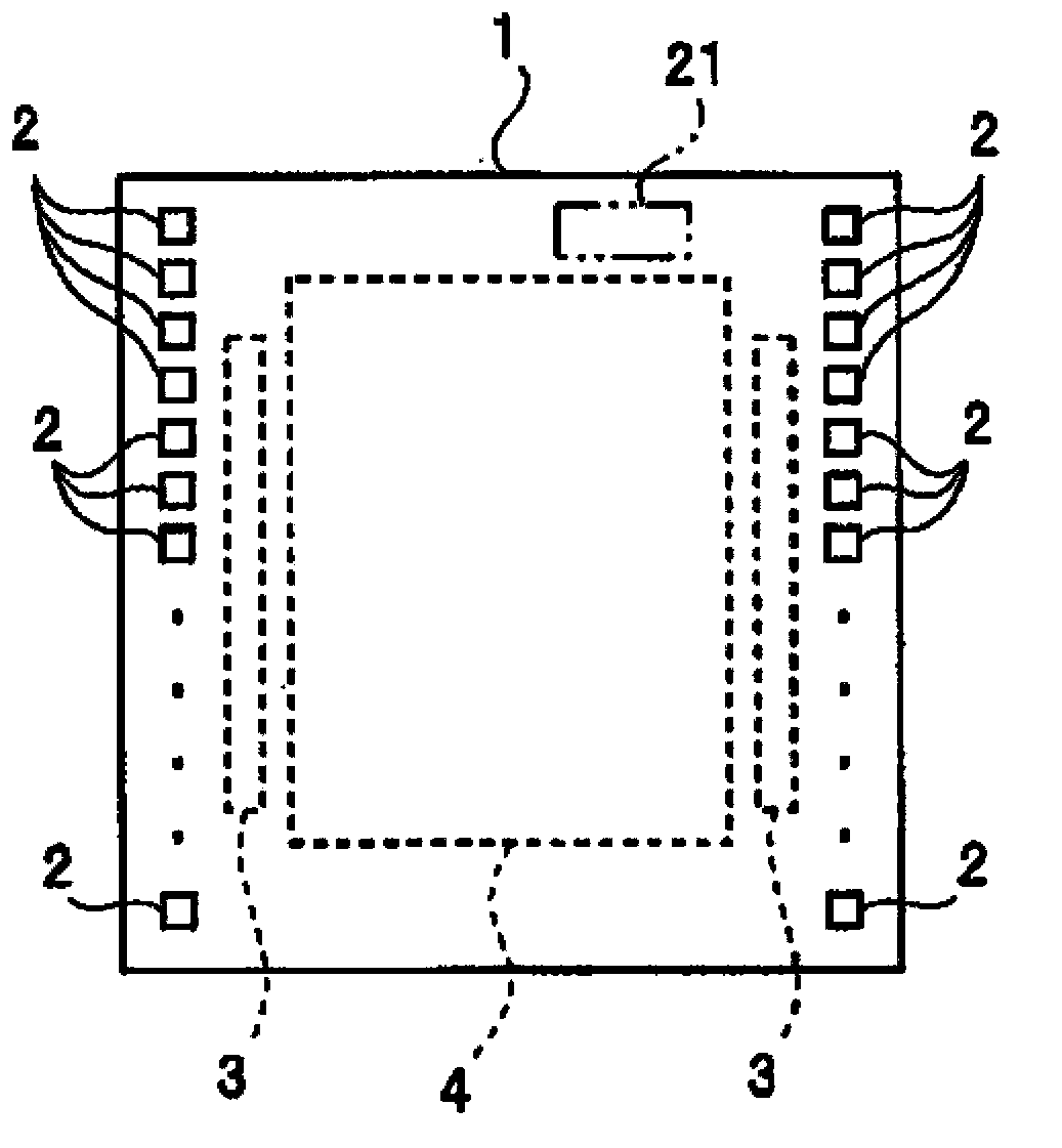
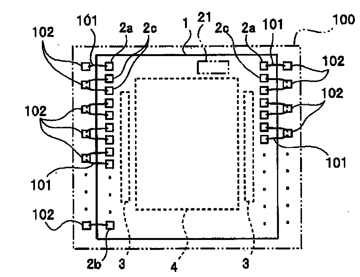
[0023] figure 1 It is a figure showing the concept of the chip layout of the semiconductor device of this embodiment. figure 2 It is a figure for explaining the state in which the semiconductor device of this embodiment is mounted on the semiconductor package.

[0024] In the semiconductor chip (hereinafter simply referred to as chip) 1 of this embodiment, if figure 1 As shown, in both peripheral portions of a rectangular chip, for example, a plurality of pads 2 for connecting bonding wires are arranged linearly along both sides of the chip 1 .

[0025] In addition, here, the plurality of bonding pads 2 are arranged in a linear shape at the peripheral portions of both sides of the chip 1 having a rectangular shape, but the plurality of bonding pads 2 may also be arranged at the peripheral portions of the four sides, or not only at the peripheral portions. .

[0026] Some pad...


PUM


Abstract

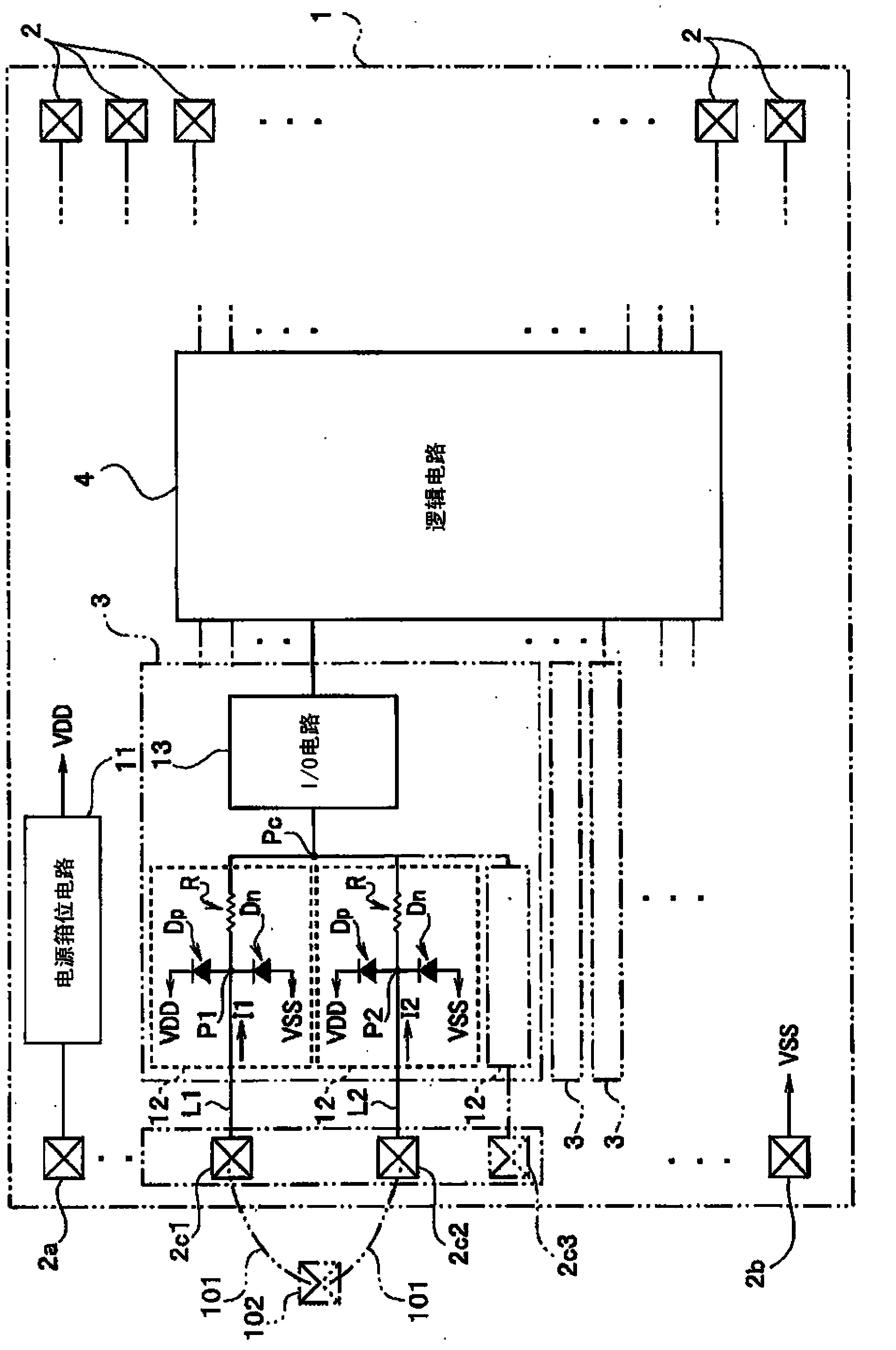
The invention provides a semiconductor device of ESD resistance while the width of the wiring pattern is not increased and the pin level of a chip of the semiconductor device is improved. A semiconductor device according to an embodiment includes a plurality of pads, a plurality of ESD protection circuits, each one of the ESD protection circuits being connected to a corresponding one of the plurality of pads, and an I / O circuit which is connected to a connection portion connecting output terminals of the plurality of ESD protection circuits to each other and which receives at least one input signal inputted into the plurality of pads.

Description

[0001] This application enjoys the priority of Japanese Patent Application No. 2012-198792 filed on September 10, 2012, and the entire content of the Japanese Patent Application is cited in this application. technical field [0002] Embodiments of the present invention relate to semiconductor devices. Background technique [0003] In electronic equipment, ESD countermeasures are taken to protect circuits from electrostatic destruction caused by electrostatic discharge (Electro-Static Discharge: hereinafter referred to as ESD). [0004] In order to evaluate ESD countermeasures, ESD resistance evaluations have been performed based on HBM (human body model) and MM (machine mode) according to the level of equipment or modules. For example, a voltage of 2KV to 3KV is applied under HBM and a voltage of 200V is applied under MM to a device or module to be evaluated, and ESD resistance evaluation is performed. [0005] In addition, for the level of electronic equipment or modules e...

Claims


Application Information

Patent Timeline
Patent Type & Authority Applications(China)
IPC IPC(8): H01L27/02H01L23/488
CPCH02H9/04H02H9/046H01L2224/05554
Inventor 濑田涉二
Owner KK TOSHIBA
Learn More