
Flexible battery pack

A flexible battery pack and battery pack technology, applied in battery pack components, small-sized batteries/battery packs, large-size batteries/battery packs, etc., can solve the bending degree and capacity limitations of battery packs, flexible battery packs Irregular bending, reducing battery energy density and other issues, to achieve the effect of reducing irregular bending, prolonging battery life, and increasing energy density

Active Publication Date: 2014-03-26
NINGDE AMPEREX TECH +1
View PDF7 Cites 32 Cited by
  • Summary
  • Abstract
  • Description
  • Claims
  • Application Information

AI Technical Summary

Problems solved by technology

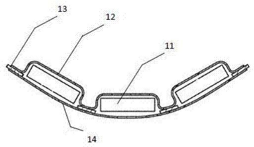
[0004] In order to meet the diverse needs of mobile portable devices for battery shapes, people mainly implement them in the following two ways: one is to use special-shaped batteries. Manufacturing method, this kind of special-shaped battery can be applied to mobile portable devices with specific shape requirements, but because it is not flexible, it is not suitable for occasions such as watches; the second is to design battery packs with variable shapes, such as Apple’s The patent application whose application number is US20130171490A1 discloses a flexible battery pack, such as figure 1 and figure 2 As shown, it arranges a series of batteries 11 on the bottom layer 14, then arranges the adhesive layer 13 between the batteries 11 and the batteries 11, and then places the top layer 12 on the battery 11; or first on the battery 11 The top layer 12 is set, the bottom layer 14 is set under the battery 11, and then the bottom layer 14 and the top layer 12 of each battery 11 are bonded together with an adhesive layer 13, so that the batteries 11 are isolated from each other, thereby preparing a flexible battery Group
[0005] However, when the flexible battery disclosed in this application is bent, because the top layer 12 and the bottom layer 14 are relatively rigid and affected by stress, the bending degree and capacity of the battery pack are greatly limited.
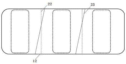
At the same time, due to uneven force, it will not be folded at the expected center of the cell 22 (ideal fold), and irregular creases shown by the fold line 23 (actual fold) may appear every time it is bent, which will cause As a result, the flexible battery pack will be bent irregularly. Long-term use will cause the battery core to be squeezed by external forces, which will affect the performance of the battery. will reduce the energy density of the battery

Method used


Image

  • Flexible battery pack
  • Flexible battery pack
  • Flexible battery pack

Examples


Embodiment 1

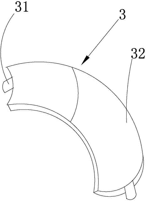
[0044] Such as Figure 5As shown, the flexible battery pack provided by this embodiment includes a packaging film 5, an electrolyte filled in the packaging film 5, and at least two electrically connected electric cores packaged in the packaging film 5, and the electric core includes a flexible battery pack. Core 3 and two conventional batteries 4, the flexible battery 3 has a bendable arc of 60° (that is, the flexible battery 3 can be bent within the range of 0~60°), and the flexible battery 3 is located between the two conventional batteries 4 In between, the flexible cells 3 are respectively connected in series with two conventional cells 4, the packaging film 5 is sealed by a sealant layer 6, the material of the sealant layer 6 is polypropylene, and the sealant layer 6 is bonded to the package by bonding and screen printing. The film 5 is packaged, and the packaging film 5 between the flexible cell 3 and the conventional cell 4 is provided with a narrowing 7 for stress rele...

Embodiment 2

[0048] Such as Figure 8 As shown, the difference from Example 1 is that the bendable arc of the flexible cell 3 is 120° (that is, the flexible cell 3 can be bent within the range of 0-120°), and the material of the sealant layer 6 is polyimide , and there is a buffer rubber layer 8 between the flexible battery 3 and the conventional battery 4, and the material of the buffer rubber layer 8 is acrylic resin to ensure that the flexible battery 3 and the conventional battery 4 are in the mutual extrusion process Stress relief, thereby reducing safety concerns. And the flexible battery cells 3 are respectively connected in parallel with two conventional battery cells 4 .

[0049] The rest are the same as in Embodiment 1, and will not be repeated here.

[0050] When preparing the flexible battery pack of this embodiment, the flexible battery 3 and the two conventional batteries 4 can be placed in the packaging film 5 respectively, and the flexible battery 3 is placed between the ...

Embodiment 3

[0052] Such as Figure 9 As shown, the difference from Example 1 is that the bendable arc of the flexible cell 3 is 30° (that is, the flexible cell 3 can be bent within the range of 0-30°), and the material of the sealant layer 6 is acrylic resin , and the battery cell includes a flexible battery cell 3 and a conventional battery cell 4, and the flexible battery cell 3 and the conventional battery cell 4 are connected in series.

[0053] The rest are the same as in Embodiment 1, and will not be repeated here.

[0054] When preparing the flexible battery pack of this embodiment, the flexible battery cell 3 and the conventional battery cell 4 can be placed in the packaging film 5 first, and the flexible battery tab 31 and the conventional battery tab 41 both protrude from the packaging. In the film 5, and the flexible battery tab 31 and the conventional battery tab 41 of the conventional battery 4 are connected in series, after the top sealing operation is performed on the pack...


PUM

PropertyMeasurementUnit
angleaaaaaaaaaa

Abstract

The invention belongs to the technical field of batteries and in particular relates to a flexible battery pack. The flexible battery pack comprises a packaging film, an electrolytic solution filled in the packaging film, and at least two electrically connected battery cells packaged in the packaging film, wherein at least one of the battery cells is a flexible battery cell. Compared with the prior art, the flexible battery pack has the characteristics that the flexible battery cells are arranged in the battery pack to serve as flexible parts, so that the battery bending phenomenon is caused at the flexible battery cells, the influence of a stress on the performance of the battery cells can be avoided, the battery stability is improved, and the bending capability of the battery pack is enhanced; moreover, the irregular bending phenomena and the bending pressure of the packaging film can be reduced, so that the service life of the battery pack is prolonged; in addition, flexible batteries are referenced in the battery pack, so that the use of external structures such as a bonding layer and the like can be reduced, the utilization rate of space in the packaging film is increased, the battery energy density is further increased, and the battery cruising duration is prolonged.

Description

technical field [0001] The invention belongs to the field of battery technology, and more specifically, the invention relates to a flexible battery pack. Background technique [0002] With the technical development of mobile and convenient devices and the increase of people's demand for mobile and portable devices, people's demand for secondary batteries as energy suppliers for mobile and portable devices has increased dramatically. With the thinning, miniaturization and diversification of shapes of mobile portable devices, secondary batteries with high energy density, high discharge voltage, special-shaped batteries, and variable shapes have become a research hotspot. [0003] At present, the research on improving the energy density and discharge voltage of secondary batteries mainly focuses on the following aspects: first, in terms of battery shape, making thin batteries or even ultra-thin batteries; Positive electrode materials, negative electrode materials, etc., or pos...

Claims


Application Information

Patent Timeline
Patent Type & Authority Applications(China)
IPC IPC(8): H01M10/04H01M2/02H01M50/102H01M50/105H01M50/121H01M50/131H01M50/136H01M50/186H01M50/193H01M50/198H01M50/509H01M50/51H01M50/512
CPCH01M10/0436H01M50/193H01M50/186H01M50/105H01M50/51H01M50/136H01M50/509H01M50/512H01M50/198H01M10/0445Y02E60/10H01M50/124Y02P70/50
Inventor 罗宇曾巧
Owner NINGDE AMPEREX TECH
Learn More