
Novel wire clamping disc

A new type of clamping disc technology, applied in the field of new clamping discs, can solve the problems of uneven force on the two wires, small contact area, oxygen absorption corrosion, etc., and achieve the effects of reducing safety hazards, high safety, and avoiding breakage

Inactive Publication Date: 2014-03-26
STATE GRID SHANDONG ELECTRIC POWER
View PDF4 Cites 6 Cited by
  • Summary
  • Abstract
  • Description
  • Claims
  • Application Information

AI Technical Summary

Problems solved by technology

[0007] For this reason, the technical problem to be solved by the present invention is that in the prior art, the two wires in the U-shaped chuck are unevenly stressed, the contact area is small, which makes it prone to hydrogen evolution corrosion or oxygen absorption corrosion, and there are potential safety hazards, thereby providing a A new type of clamping disc with uniform force, larger contact surface, closer contact and high safety

Method used


Image

  • Novel wire clamping disc
  • Novel wire clamping disc

Examples


Embodiment 1

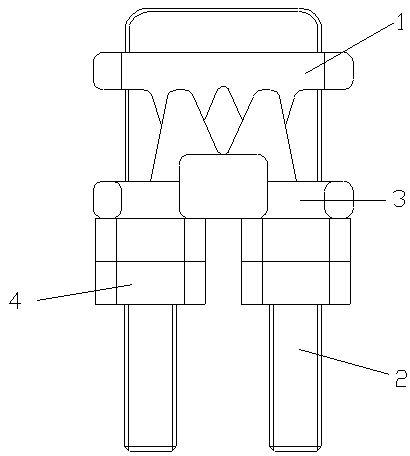
[0027] A new type of clamping disc according to the present invention, such as figure 1 As shown, it includes a U-shaped pressure ring 2 and a cover part 3 inserted from both ends of the U-shaped pressure ring 2, and the cover part 3 is preferably provided with the size of the two ends of the U-shaped pressure ring 2. Corresponding to the two through holes, the two ends of the U-shaped pressure ring 2 pass through the cover part 3 through the two through holes, and the end of the U-shaped pressure ring 2 is provided with a clamp to clamp the cover part 3, the clamping component 4 can move on the U-shaped pressure ring 2 to cooperate with the movement of the cover part 3, and the cover part 3 is provided with a clamping cable Draw-in slot, on the two side walls of the U-shaped pressure ring 2, a base 1 for supporting the cable is clamped, and the base 1 is provided with a groove for accommodating the cable, and the groove and the draw-in slot Cooperate to clamp the cable, and ...

Embodiment 2

[0029] On the basis of a new clamp disc described in Example 1, the end of the U-shaped pressure ring 2 is provided with threads, and the clamping part 4 is preferably a nut, and the nut is screwed on On the thread at the end of the U-shaped pressure ring 2, using a commonly used nut can effectively reduce the cost, which is a wider application of the present invention.

[0030] The base 1 is provided with locking slots for clamping the side walls of both sides of the U-shaped pressure ring 2, which can further fix the base 1 and the U-shaped pressure ring 2 to prevent the base 1 from being in the U-shaped The movement in the pressure ring 2 avoids the situation that the base 1 slips from the U-shaped pressure ring 2 in practical application, which increases the safety.

Embodiment 3

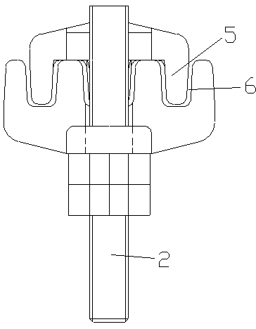
[0032] On the basis of a new type of clamping disc described in the above embodiments, as figure 2 As shown, the sidewalls on both sides of the card slot and the sidewalls on both sides of the groove have joint surfaces, and the joint surface is provided with a protruding part 5 and a concave part 6 that cooperate with each other, and the protruding part 5 It can be set on the cover part 3 or on the base 1, the recessed part 6 is set on the surface corresponding to the raised part 5, and the raised part 5 and the The setting of the recessed part 6 makes the cover part 3 and the base 1 have a claw-shaped structure; in the present invention, three protrusions 5 are preferably arranged on the side walls of the groove on both sides of the base 1, and the Three recessed parts 6 are provided on the two side walls of the card slot of the cover part 3, and the three raised parts 5 can be inserted into the three recessed parts 6 correspondingly, so that the base 1 and the cover The c...


PUM


Abstract

A novel wire clamping disc includes a U-shaped pressing ring and a cover part which is inserted from two end parts of the U-shaped pressing ring. The end part of the U-shaped pressing ring is provided with a clamping part for clamping the cover part; the cover part is provided with a clamping groove for clamping a cable; two side walls of the U-shaped pressing ring are clamped with a base for supporting the cable; the base is provided with a groove for accommodating the cable; and the groove and the clamping groove are cooperated to clamp the cable. The problems in the prior art that two wires in the U-shaped clamping head have uneven stress, that the small contact area results in the easy hydrogen evolution corrosion or oxygen uptake corrosion, and that the potential safety hazard exists are solved, and the novel wire clamping disc with the uniform stress, larger contact area, firmer contact, and higher security is provided.

Description

technical field [0001] The invention relates to a wiring connection device, in particular to a new clamping disc. Background technique [0002] In the various overhead lines currently in operation, the grounding downconductor of each base tower (cement pole) is connected to the lightning protection line at the pole head through a U-shaped chuck (commonly known as iron chuck, cassette, and clamping reel). During the operation of the U-shaped clamp, we found that the lightning conductor and the grounding down-conductor are particularly prone to rust and corrosion at the U-shaped clamp, and the two wires in the clamp are severely broken. [0003] What is widely used in the prior art is a utility model patent named "Wire Rope Chuck Device" such as Chinese Patent No. 201220305553.4, which includes a mountain-shaped base and a U-shaped pressure ring. The mountain-shaped base is provided with a through hole, and the U-shaped The opening end of the U-shaped pressure ring passes thr...

Claims


Application Information

Patent Timeline
IPC IPC(8): H02G7/20
Inventor 郝宗鸣齐蔚海周相成王志强
Owner STATE GRID SHANDONG ELECTRIC POWER
Features
  • Generate Ideas
  • Intellectual Property
  • Life Sciences
  • Materials
  • Tech Scout
  • Unparalleled Data Quality
  • Higher Quality Content
  • 60% Fewer Hallucinations
Learn More