Ceiling fan motor

A ceiling fan, motor shaft technology, applied in electrical components, electromechanical devices, electric components, etc., can solve the problems of loose overall space inside the motor, complex motor structure, increased use cost, etc., to achieve full utilization of the overall space and shorten the production process time. , the effect of reducing production costs

Active Publication Date: 2014-03-26
NINGBO HUJIANG ELECTRIC MOTOR
View PDF9 Cites 5 Cited by
  • Summary
  • Abstract
  • Description
  • Claims
  • Application Information

AI Technical Summary

Problems solved by technology

[0003] At present, the structures of existing ceiling fan motors are basically the same, and the principles are basically the same. Shaft, motor stator, motor rotor, upper bearing, lower bearing, a cavity is formed between the upper motor shell and the lower motor shell, the motor shaft runs through the upper motor shell and the lower motor shell, and the motor stator, upper bearing, and lower bearing are installed from top to bottom On the motor shaft, the upper bearing is fixedly connected with the inner wall of the motor upper shell, the lower bearing is fixedly connected with the inner wall of the lower motor shell, and the motor rotor is connected with the inner wall of the upper motor shell and the lower shell of the motor at the same time. The motor rotor is located on the periphery of the motor stator and the motor The inner wall of the rotor fits the outer wall of the motor stator. After the power is turned on, the motor stator is fixed, and the motor rotor rotates around the periphery of the motor stator and drives the motor upper shell and the motor lower

Method used


Image

  • Ceiling fan motor
  • Ceiling fan motor
  • Ceiling fan motor

Examples


Example Embodiment

[0026] The following are specific embodiments of the present invention combined with the accompanying drawings to further describe the technical solutions of the present invention, but the present invention is not limited to these embodiments.
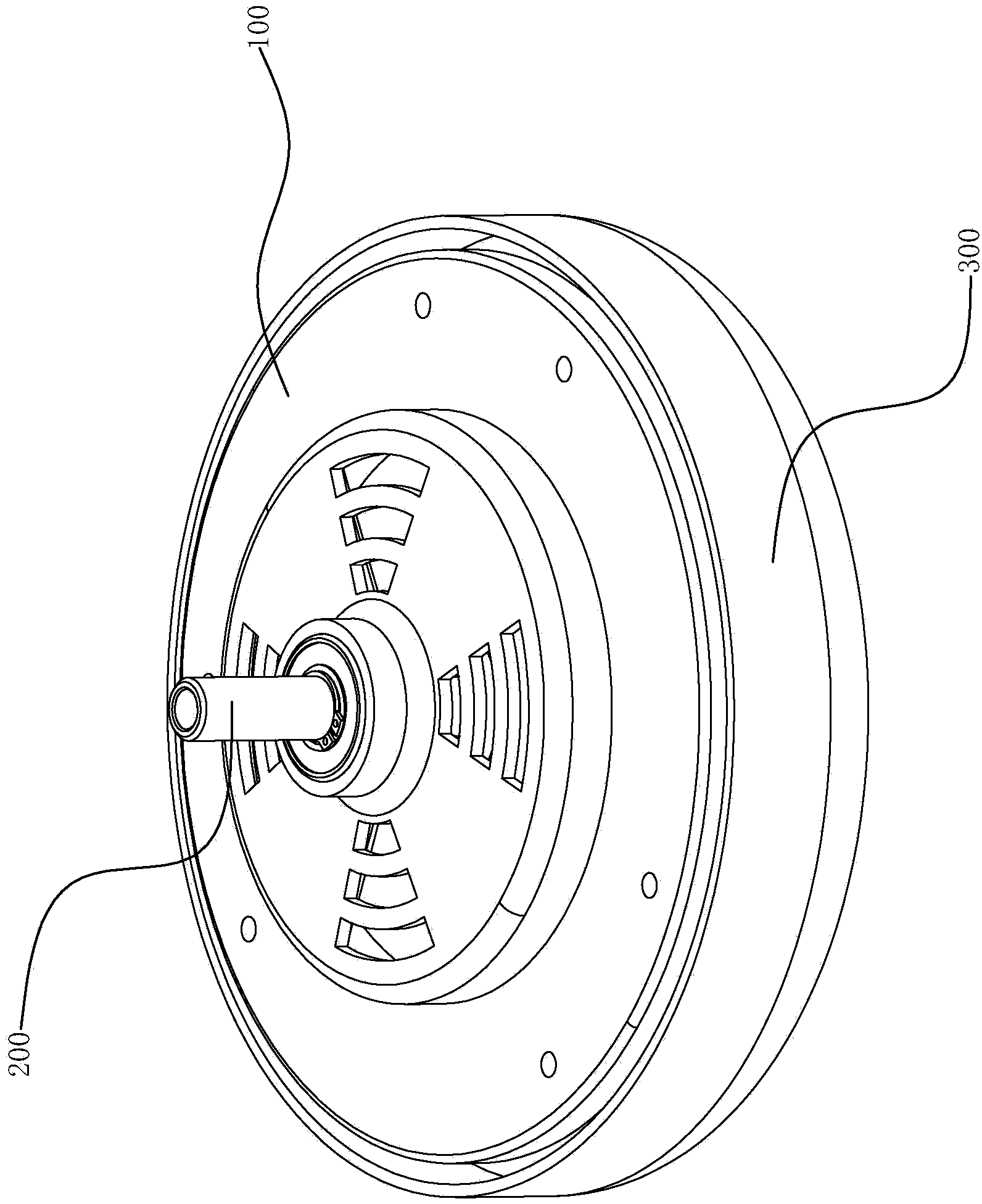
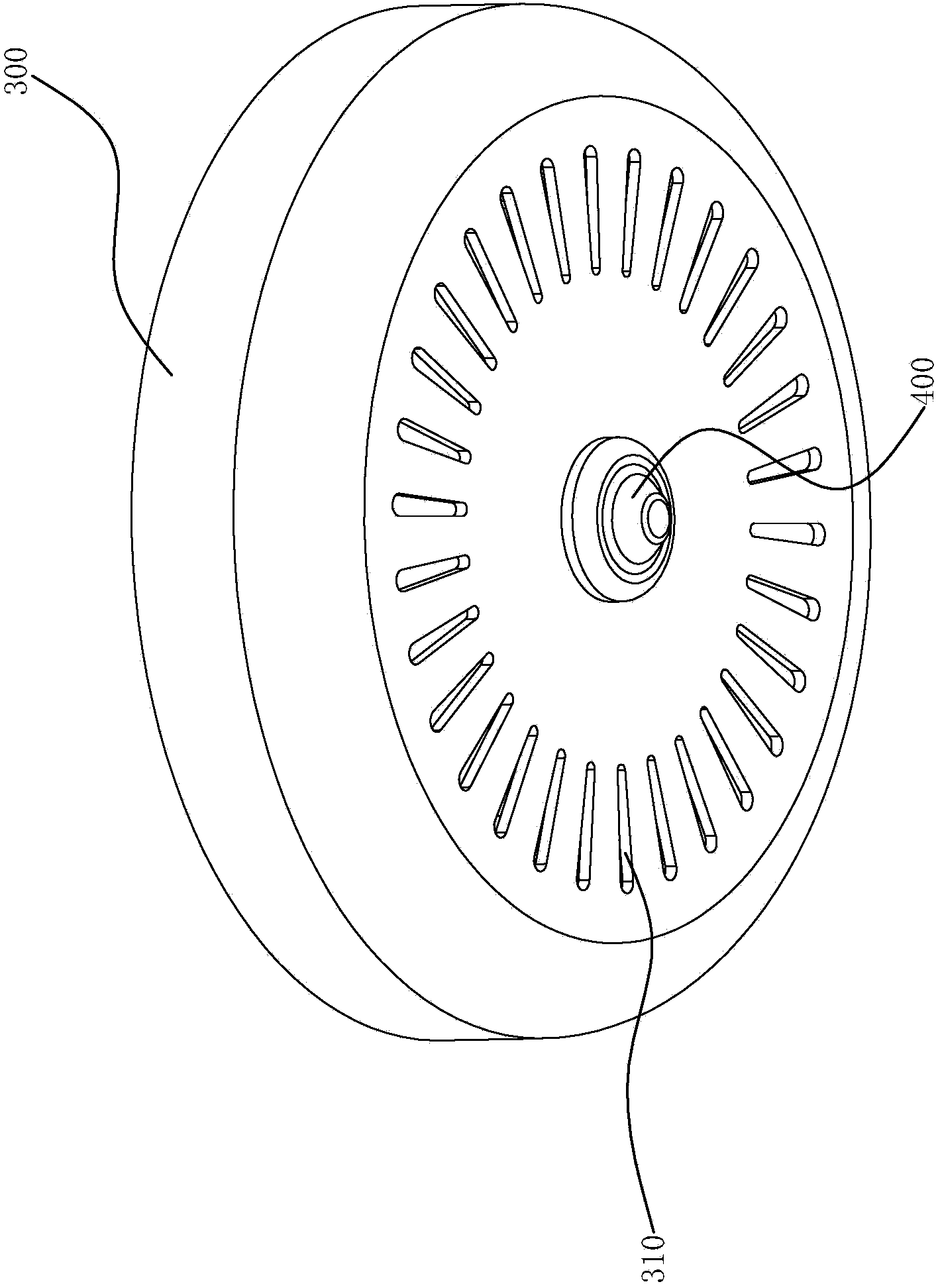
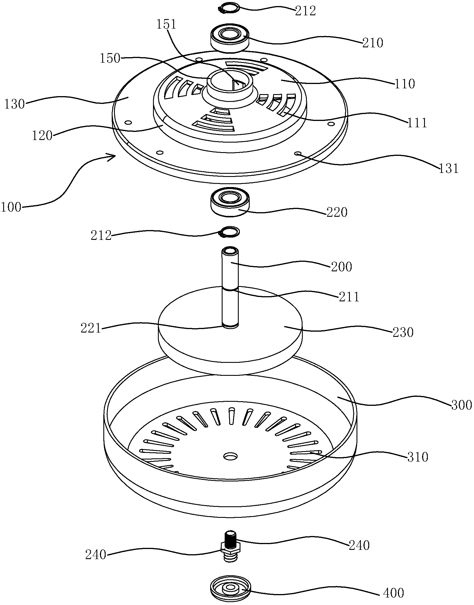
[0027] Such as figure 1 with figure 2 As shown, a ceiling fan motor of the present invention includes an end cover 100, a motor shaft 200, and a bottom cover 300. The end cover 100 is generally circular. The end cover 100 is mainly composed of a circular top cover 110, an annular connecting portion 120, and an annular The peripheral edge portion 130 is composed of and the three are integrally formed. The circular top cover 110 is arranged horizontally, and the annular connecting portion 120 is located on the periphery of the circular top cover 110 and extends vertically downward from the periphery of the circular top cover 110. The annular peripheral edge portion 130 is also It is arranged horizontally, and the upper surface of the inner ...


PUM


Abstract

The invention provides a ceiling fan motor, and belongs to the technical field of motors. The ceiling fan motor solves the technical problems that an existing ceiling fan motor is large in size, complicated in structure and high in production and use cost. According to the technical scheme, the ceiling fan motor comprises an end cap, a motor shaft, a first bearing, a second bearing, a stator and a rotor, wherein the middle of the end cap is vertically provided with a shaft barrel penetrating through the end cap, the two ends of the shaft barrel extend to the outside of the upper surface of the end cap and the outside of the lower surface of the end cap respectively, the first bearing and the second bearing are fixedly arranged at the upper end and the lower end of the inside of the shaft barrel respectively, the motor shaft penetrates through the shaft barrel, the first bearing and the second bearing are arranged on the motor shaft in a sleeved mode, the stator is fixedly arranged on the motor shaft in a sleeved mode, the rotor is fixedly arranged on the lower surface of the end cap and located on the periphery of the stator, the inner side wall of the rotor and the outer side wall of the stator are separated, and the rotor rotates on the periphery of the stator and enables the end cap, the first bearing and the second bearing to rotate synchronously. The ceiling fan motor is simpler in structure, production and use cost is reduced, accuracy is improved and the ceiling fan motor operates more stably.

Description

technical field [0001] The invention belongs to the technical field of motors, and relates to a ceiling fan motor. Background technique [0002] A ceiling fan is a fan that is fixed on the ceiling and has a good cooling effect. The ceiling fan generally includes a ceiling fan motor and three fan blades fixed on the ceiling fan motor. The ceiling fan motor is used as a power source to drive the fan blades to rotate and generate a large The wind is used to cool off the heat, so the ceiling fan motor is the most important part of the ceiling fan. [0003] At present, the structures of existing ceiling fan motors are basically the same, and the principles are basically the same. Shaft, motor stator, motor rotor, upper bearing, lower bearing, a cavity is formed between the upper motor shell and the lower motor shell, the motor shaft runs through the upper motor shell and the lower motor shell, and the motor stator, upper bearing, and lower bearing are installed from top to botto...

Claims


Application Information

Patent Timeline
IPC IPC(8): H02K5/04H02K5/16H02K5/20H02K7/14
Inventor 陈洪飞杨源欣
Owner NINGBO HUJIANG ELECTRIC MOTOR
Why Eureka
Try Eureka