System for driving electromagnetic appliance and motor driven vehicle

A technology for device driving and electric motors, which is applied in the control of motor vibration, electronic commutation motor control, motor vehicles, etc., and can solve problems such as difficulty in dealing with common mode noise.

Inactive Publication Date: 2014-03-26
KK TOSHIBA
View PDF8 Cites 1 Cited by
  • Summary
  • Abstract
  • Description
  • Claims
  • Application Information

AI Technical Summary

Problems solved by technology

However, at the end of the dead time, it is difficult to deal with the common mode noise caused by the high-frequency f...

Method used


Image

  • System for driving electromagnetic appliance and motor driven vehicle
  • System for driving electromagnetic appliance and motor driven vehicle
  • System for driving electromagnetic appliance and motor driven vehicle

Examples


no. 1 Embodiment approach )

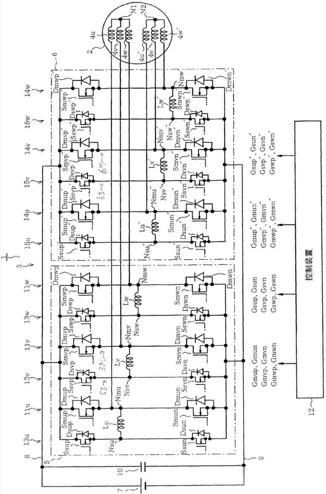
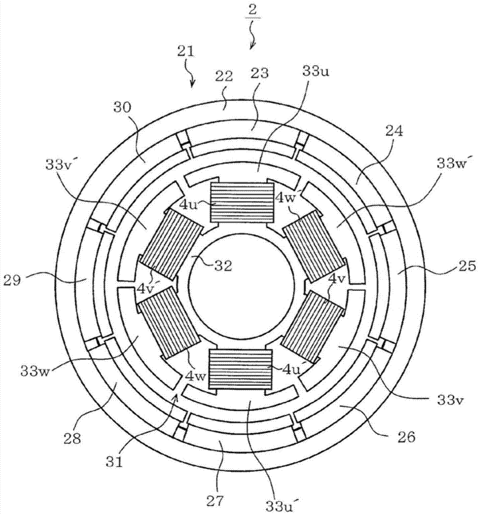
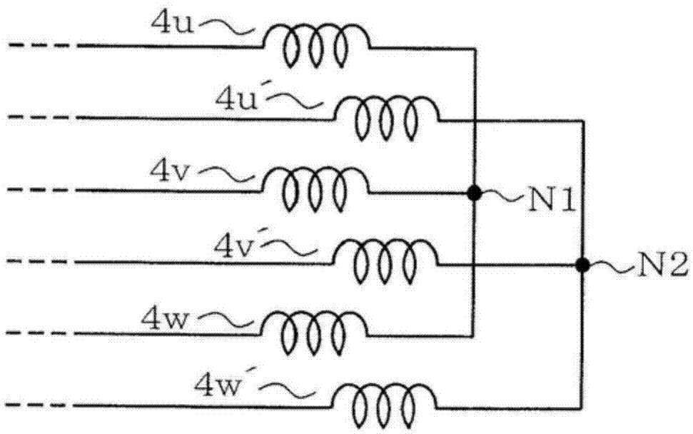
[0026] Below, refer to Figure 1 to Figure 12 , a first embodiment of a system for driving a motor as an electromagnetic device will be described. figure 1 The illustrated motor drive system 1 includes a motor 2 and a drive device 3 for driving the motor 2 . The motor 2 is, for example, a three-phase brushless DC motor, and includes first windings 4u, 4v, 4w and second windings 4u', 4v', 4w' as pairs of three-phase (n=3) stator windings. Details will be described later, but the winding structure of the motor 2 is such that the rotor rotates in the same direction when three-phase currents of opposite phases flow through the first windings 4u to 4w and the second windings 4u' to 4w'. Here, the motor 2 having the above structure is referred to as a "3-phase motor".

[0027] The drive device 3 includes a first power conversion device 5 and a second power conversion device 6 in parallel. Both the first power conversion device 5 and the second power conversion device 6 convert DC...

no. 2 Embodiment approach )

[0110] Figure 14 to Figure 17 In order to explain the drawings of the second embodiment, the same reference numerals are assigned to the same parts as those of the first embodiment, and description thereof will be omitted, and different parts will be described below. The driving device 51 constituting the transformer driving system 50 of the second embodiment includes a third power converting device 52 in addition to the first and second power converting devices 5 and 6 . The third power conversion device 52 is a DC-DC converter and includes a main half-bridge circuit 53 and an auxiliary half-bridge circuit 54 connected between the DC power supply lines 8 and 9 .

[0111] The main half-bridge circuit 53 is composed of a series circuit of main switching elements Smxp and Smxn, and the auxiliary half-bridge circuit 54 is composed of a series circuit of auxiliary switching elements Ssxp and Ssxn. Main freewheeling diodes Dmxp and Dmxn are respectively connected in antiparallel ...


PUM


Abstract

In one embodiment, system for driving an electromagnetic appliance includes an electromagnetic appliance, a main-drive unit and a sub-drive unit. The electromagnetic appliance includes coils for n number of phases, the coils for each of the n phases being arranged in a pair and wound so as to be excited in a predetermined direction by being energized with opposite-phase currents. The main drive unit is connected to each of the coils and energizes the paired coils with opposite-phase currents. The sub-drive unit is provided parallel with the main-drive unit and is configured to suppress a short-circuit current occurring at the main-drive unit when switching energization of the coils.

Description

technical field [0001] Embodiments of the present invention relate to an electromagnetic device drive system and a motor-driven vehicle using the electromagnetic device drive system. Background technique [0002] For example, a power conversion device for driving a 3-phase motor is configured such that a 3-phase half-bridge circuit is connected in parallel between positive and negative DC power supply lines. The half-bridge circuit is composed of a pair of semiconductor switching elements connected in series between the DC power lines and freewheeling (Japanese original: recirculation) diodes connected in antiparallel to these semiconductor switching elements. In the power conversion device configured as described above, PWM (Pulse Width Modulation, pulse width modulation) control is performed on driving of each semiconductor switching element. Thereby, the DC power supplied from the DC power supply line is converted into three-phase AC power, and a sinusoidal current flows...

Claims


Application Information

Patent Timeline
IPC IPC(8): H02P6/08H02M7/48B60L3/00B60L9/18B60L50/16H02P21/05H02P23/04H02P25/22H02P27/06H02P27/08
CPCY02T10/642H02P6/001B60L2220/58H02K11/001B60L3/003B60L2210/40B60L11/1803H02P25/22Y02T10/641H02M7/5387B60L2270/147B60L11/14B60L2210/30B60L2200/26Y02T10/70H02M7/493H02P6/34B60L15/007B60L50/16B60L50/51H02M1/088H02K11/20Y02T10/64Y02T10/72Y02T10/7072H03K17/145
Inventor 筱原尚人永井一信松毛和久
Owner KK TOSHIBA
Why Eureka
Try Eureka