Light-emitting diode driving method and operation method thereof

A light-emitting diode and driving device technology, which is applied in the field of light-emitting diode driving devices, can solve problems such as increased voltage and current, large power consumption, and overheating, so as to avoid excessive power consumption and overheating, and avoid average The effect of current inaccuracy

Inactive Publication Date: 2014-03-26
RAYDIUM SEMICON
View PDF4 Cites 0 Cited by
  • Summary
  • Abstract
  • Description
  • Claims
  • Application Information

AI Technical Summary

Problems solved by technology

[0003] However, since the set voltage output from the set voltage generator in the prior art to the current source circuit at the lower end of the light-emitting diode varies with the input voltage, as Figure 1A to Figure 1C As shown, from the waveform diagram of its input voltage, light-emitting diode current and power consumption, it can be seen that: the light-emitting diode current (ILED) will change with the input voltage. When the input voltage becomes larger, the light-emitting diode The current also increases accordingly, which leads to the inaccurate current of the light-emitting diode current under different input voltages (high input voltage VH and low input voltage VL), that is, the problem of poor input voltage regulation (Line Regulation)
In addition, since the voltage and current of the current source circuit arranged at the lower end of the light-emitting diode will increase, the power consumption will be too large, resulting in the problem of overheating.

Method used


Image

  • Light-emitting diode driving method and operation method thereof
  • Light-emitting diode driving method and operation method thereof
  • Light-emitting diode driving method and operation method thereof

Examples


Embodiment Construction

[0038] A specific embodiment according to the present invention is a light emitting diode driving device. In this embodiment, the LED driving device is used to drive the LED to emit light, but it is not limited thereto.

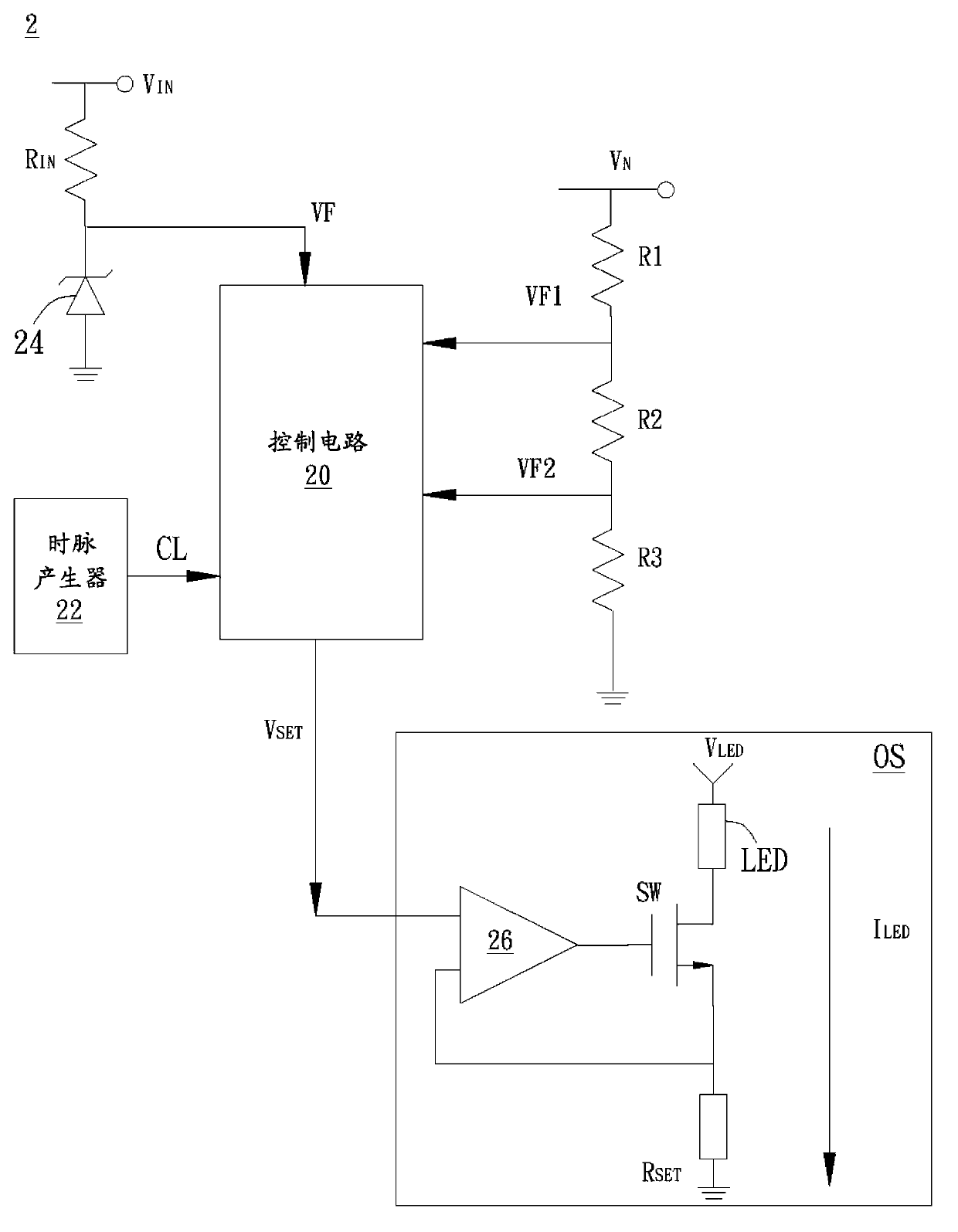
[0039] Please refer to figure 2 , figure 2 It is a schematic diagram illustrating the circuit structure of the light-emitting diode driving device of this embodiment. Such as figure 2 As shown, the light-emitting diode driving device 2 includes an output stage OS, an input resistor R IN , the control circuit 20, the clock generator 22, the regulator 24, the first voltage dividing resistor R connected in series with each other 1 , the second voltage divider resistor R 2 and the third voltage divider resistor R 3 .

[0040] Input resistance R IN One end of the coupling input voltage V IN , and the other end is coupled to the regulator 24 . The control circuit 20 is respectively coupled to the input resistor R IN and regulator 24, the first divider...


PUM


Abstract

The present invention discloses a light-emitting diode driving method and an operation method thereof. The LED driving device includes an output stage, an input resistor, a plurality of voltage dividing resistors, and a control circuit. The output stage includes at least one LED. A first voltage dividing resistor, a second voltage dividing resistor, and a third voltage dividing resistor are coupled between a specific voltage and ground in series to divide the specific voltage. A LED current passing through the LED has a duty cycle changed with the specific voltage. The control circuit senses a first voltage signal, a second voltage signal, and a third voltage signal between the first voltage dividing resistor and the second voltage dividing resistor, between the second voltage dividing resistor and the third voltage dividing resistor, and the input resistor respectively, and adjusts a setting voltage signal outputted to the output stage by the control circuit according to the first voltage signal, the second voltage signal, and the third voltage signal.

Description

technical field [0001] The present invention is related to the driving of light-emitting diodes, in particular to a driving device of light-emitting diodes and its operation method. Background technique [0002] Generally speaking, the operating principle of the traditional AC-to-DC type LED driving circuit is to use an AC to DC converter (AC to DC converter) to generate the cross voltage (input Voltage) to drive the light-emitting diode to emit light, and at the same time, a current source circuit is set at the lower end of the light-emitting diode to control the fixed current flowing through the light-emitting diode to the ground terminal, thereby stabilizing the luminance of the light-emitting diode. Since the input voltage is a rectified signal, not a DC voltage, it needs to be driven by a light-emitting diode driving circuit, thereby achieving a higher PF power factor and luminous efficiency. [0003] However, since the set voltage output from the set voltage generator...

Claims


Application Information

Patent Timeline
Patent Type & Authority Applications(China)
IPC IPC(8): H05B37/02H05B44/00
CPCH05B33/0821H05B33/0848H05B45/14H05B45/40
Inventor 郑忠泰林佳秀
Owner RAYDIUM SEMICON
Why Eureka
Try Eureka