Rigidity-flexibility combined circuit board of flying-tail structure and manufacturing method thereof

A technology of rigid-flex bonding and manufacturing method, applied in the direction of printed circuit manufacturing, multi-layer circuit manufacturing, printed circuit structural connection, etc., can solve the problems of easily crushed solder mask and unqualified circuit board quality.

Active Publication Date: 2014-03-26
GUANGZHOU FASTPRINT CIRCUIT TECH +2
View PDF5 Cites 15 Cited by
  • Summary
  • Abstract
  • Description
  • Claims
  • Application Information

AI Technical Summary

Problems solved by technology

Traditionally, rigid-flex circuit boards are usually laminated and then pressed out at one time, but for rigid-flex circuit boards with flying tail structures, if the traditional rigid-flex circuit board manufacturing method is used, the The solder resist layer on the second rigid area is easily crushed, resulting in unqualified circuit board quality

Method used


Image

  • Rigidity-flexibility combined circuit board of flying-tail structure and manufacturing method thereof
  • Rigidity-flexibility combined circuit board of flying-tail structure and manufacturing method thereof
  • Rigidity-flexibility combined circuit board of flying-tail structure and manufacturing method thereof

Examples


Embodiment Construction

[0038] Embodiments of the present invention are described in detail below in conjunction with accompanying drawings:

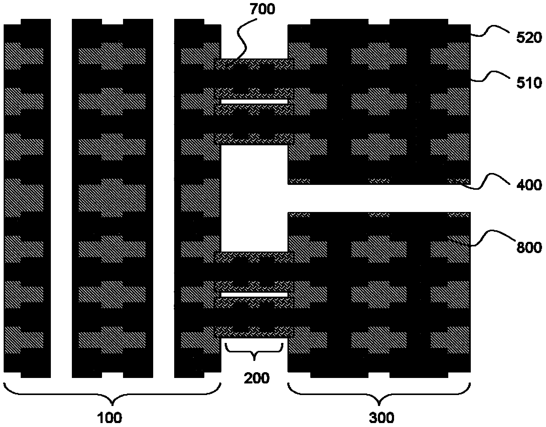
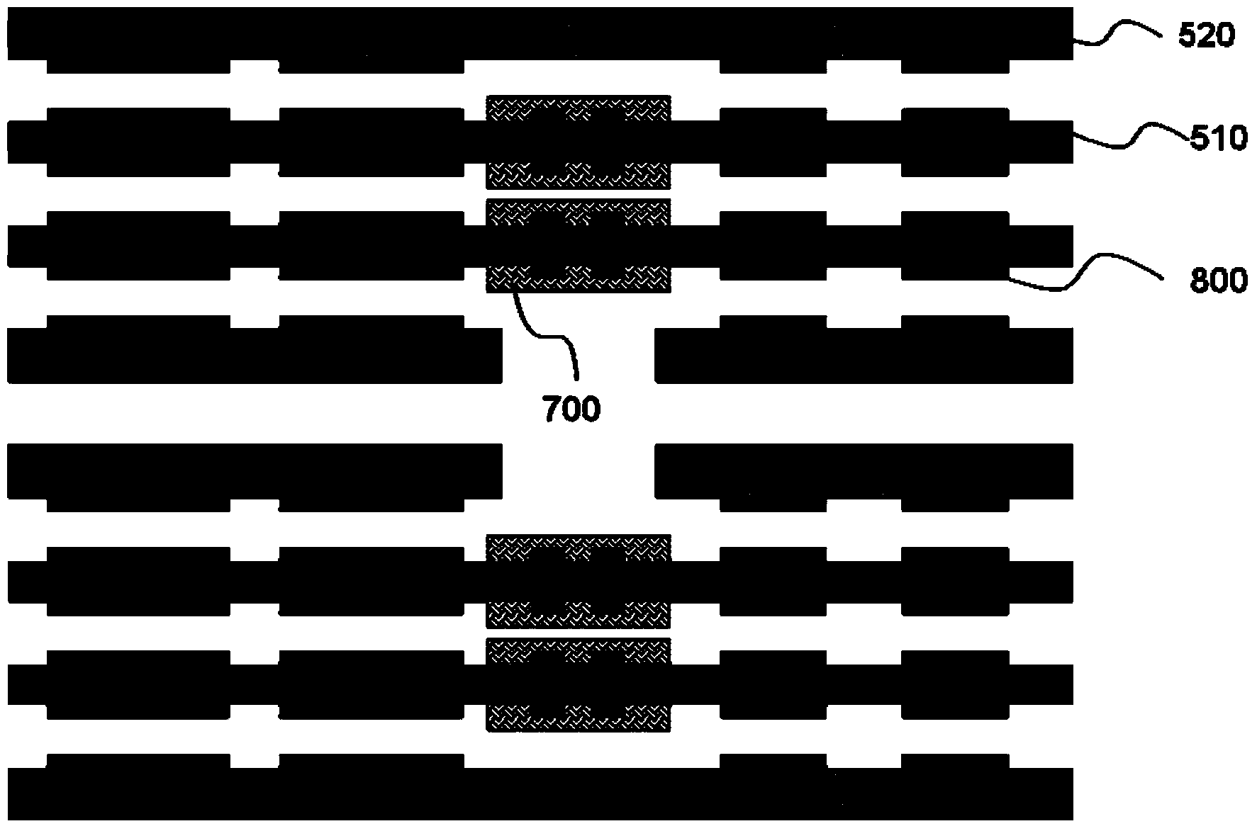
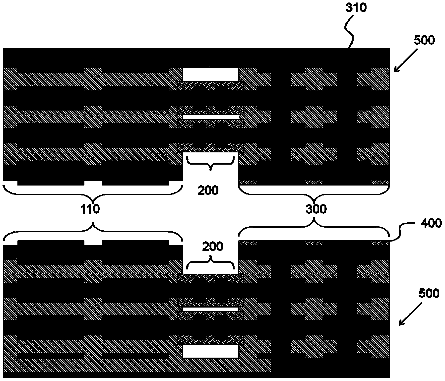
[0039] Such as figure 1 As shown, a rigid-flex circuit board with a flying tail structure includes a first rigid region 100, at least two flexible regions 200, and a second rigid region 300 equal in number to the flexible regions 200. The first rigid region One end of 100 is respectively connected to one end of the flexible zone 200, and the other end of the flexible zone 200 is respectively connected to one of the second rigid zones 300, and each second rigid zone 300 is on the solder-proof zone on the adjacent end surface. A polyetherimide cover film 400 is attached.

[0040] The rigid-flexible circuit board with the flying tail structure described in this embodiment is a rigid-flexible circuit board with sixteen layers of circuits 800, which includes two second rigid regions 300 and two flexible regions 200. The polyetherimide cover film 400 is pasted on ...


PUM


Abstract

The invention discloses a manufacturing method of a rigidity-flexibility combined circuit board of a flying-tail structure. The manufacturing method includes the following steps that step1, core boards needed by all daughter boards are manufactured, and each daughter board comprises at least one flexibility core board and at least one rigidity core board, all the core boards are stacked and laminated to manufacture the daughter boards equal to second rigidity areas in number, and each daughter board comprises a part of a first rigidity area, a flexibility area and a second rigidity area; step2, all the daughter boards obtained in the step1 are stacked, and polyetherimide covering films are pasted on anti-welding areas of adjacent end faces of all the second rigidity areas; step3, PTFE gaskets are padded between the adjacent flexibility areas and the adjacent rigidity areas, all the daughter boards processed in the step2 are laminated, and the parts of the first rigidity areas of all the daughter plates are laminated together to form the first rigidity areas. The invention further discloses the rigidity-flexibility combined circuit board of the flying-tail structure. The manufacturing method of the rigidity-flexibility combined circuit board of the flying-tail structure can effectively prevent an anti-welding layer from being damaged.

Description

technical field [0001] The invention relates to a printed circuit board manufacturing technology, in particular to a rigid-flex combined circuit board with a flying tail structure and a manufacturing method thereof. Background technique [0002] The rigid-flex circuit board is developed on the basis of rigid circuit boards and flexible circuit boards. It inherits the characteristics of rigid circuit boards and flexible circuit boards. It has small size, light weight, flexible structure, and three-dimensional Advantages such as assembly, more and more people's attention. Rigid-flex circuit boards are in line with the trend of miniaturization and portability of electronic products today, and the market demand for them is increasing day by day. [0003] The flexibility of the rigid-flex circuit board also determines the diversity of its structure. The diversity of its structure brings certain difficulties to production, especially the rigid-flex circuit board with a flying tai...

Claims


Application Information

Patent Timeline
Patent Type & Authority Applications(China)
IPC IPC(8): H05K1/02H05K1/14H05K3/36H05K3/46
CPCH05K3/4691H05K2203/061H05K2203/308H05K1/028H05K1/0298H05K1/09H05K1/115H05K3/0047H05K3/423H05K3/429H05K3/4611H05K2203/068
Inventor 邱醒亚林楚涛
Owner GUANGZHOU FASTPRINT CIRCUIT TECH
Why Eureka
Try Eureka