Arrangement for securing an energy storage module on a module support

A configuration system and energy storage technology, applied in the direction of threaded fasteners, power devices, electric power devices, etc., can solve the problems of increasing the structural space, cost, and disadvantages of energy storage modules

Active Publication Date: 2014-03-26
BAYERISCHE MOTOREN WERKE AG
View PDF8 Cites 16 Cited by
  • Summary
  • Abstract
  • Description
  • Claims
  • Application Information

AI Technical Summary

Problems solved by technology

These protrude beyond the energy storage module and thus disadvantageously increase the installation space of the energy storage module
Furthermore, this fastening method with bolts and nuts is complex in assembly

Method used


Image

  • Arrangement for securing an energy storage module on a module support
  • Arrangement for securing an energy storage module on a module support
  • Arrangement for securing an energy storage module on a module support

Examples


Embodiment Construction

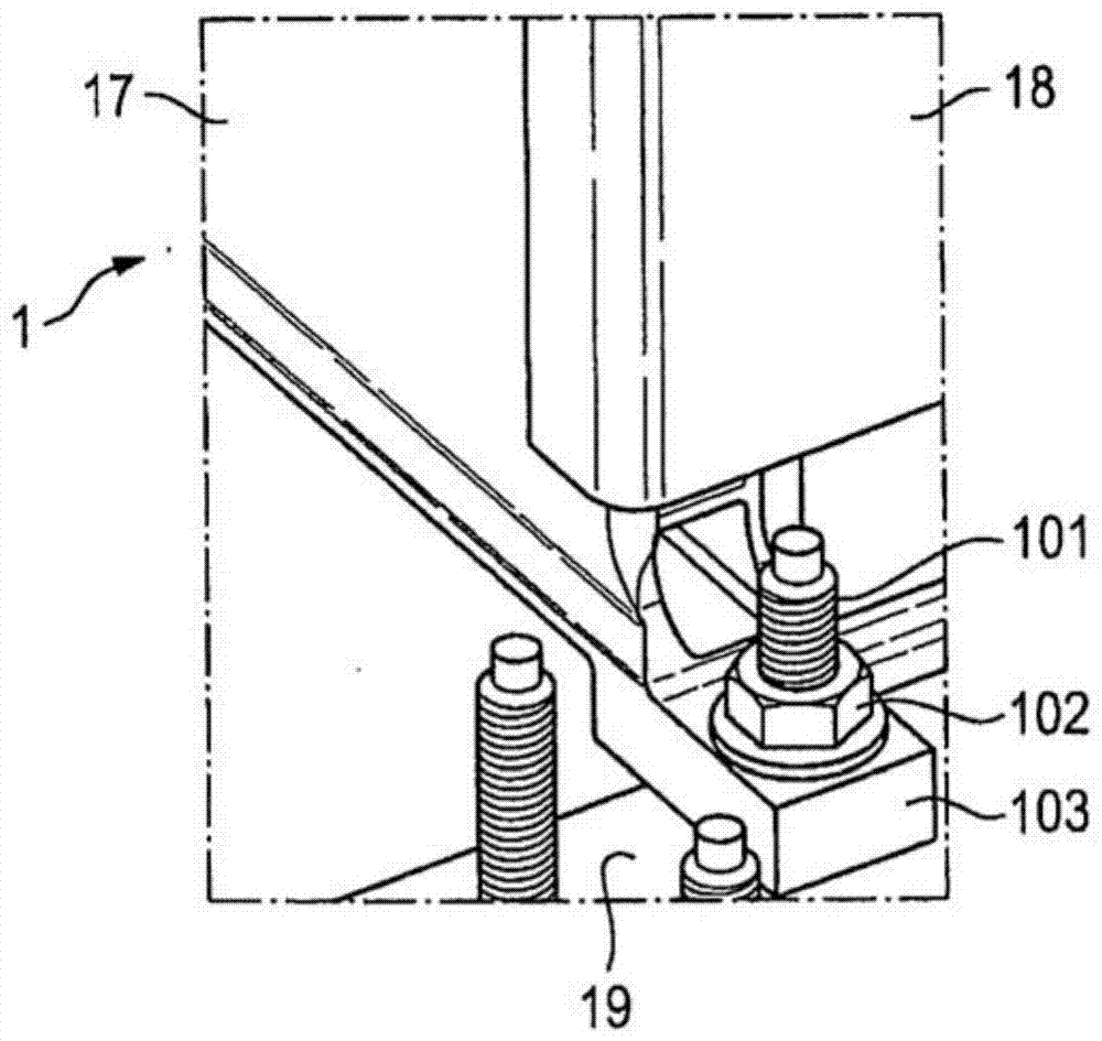
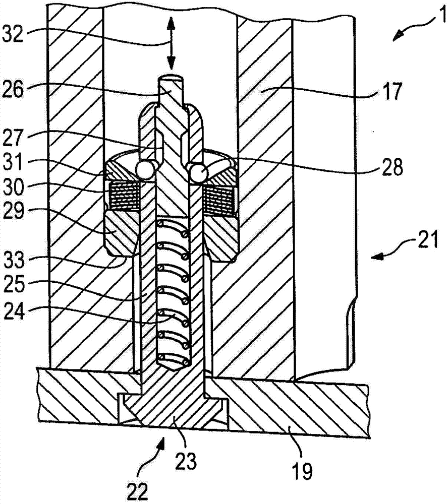
[0036] With the help of figure 1 and 3 to 7 to explain the present invention more precisely. figure 2 A conventional, not according to the invention, screw connection of the energy storage module 1 to the module carrier 19 is shown.

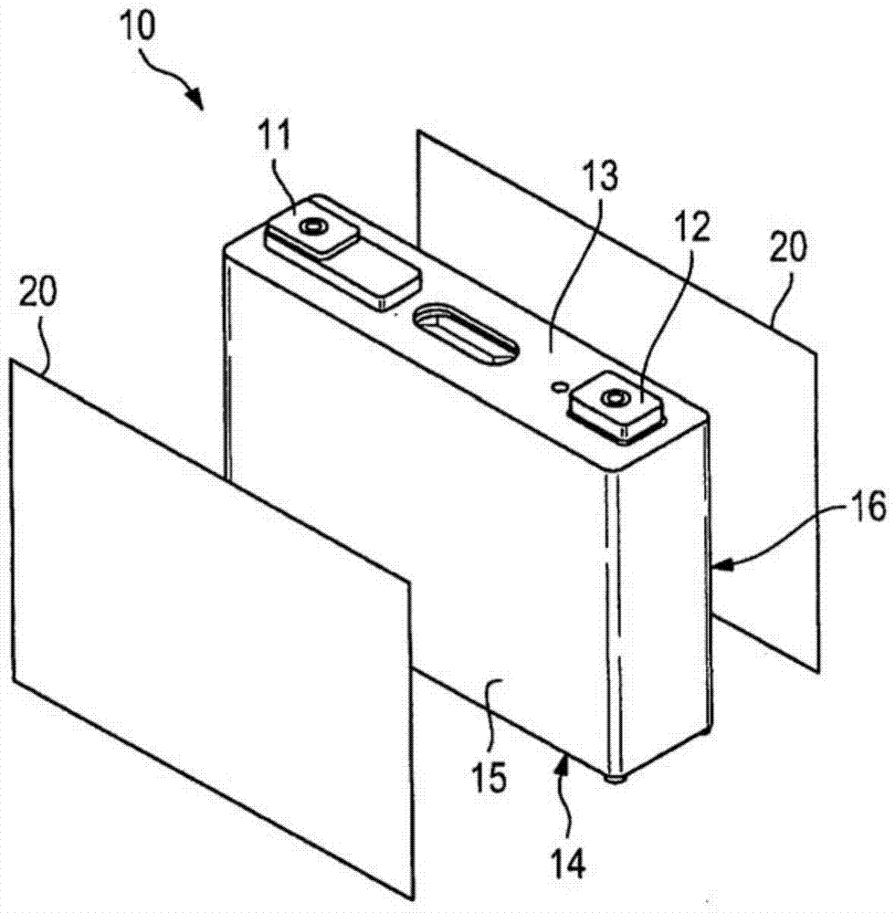
[0037] exist figure 1 A perspective view of an individual prismatic storage unit 10 of an energy storage module 1 used according to the invention can be seen in FIG. The storage unit 10 typically includes one or more individual electrochemical cells, which are concealed within the interior of the storage unit 10 in the illustration selected here. The memory cell 10 has a connection terminal 11 of a first polarity and a connection terminal 12 of a second polarity on a front side 13 . in storage unit 10 in the figure 1 No connection terminals are provided on the rear side 14 (not shown). One of the connection terminals 11 , 12 of the storage unit 10 , typically the positive pole, can be electrically connected to the housing of the storage ...


PUM


Abstract

The invention relates to an arrangement (21) which comprises an energy storage module (1), a module support (19), in particular a vehicle body, and a ball lock pin (22) designed for securing the energy storage module (1) on the module support (19).

Description

technical field [0001] The invention relates to an arrangement system for fastening an energy storage module to a module carrier, in particular a vehicle body. Background technique [0002] In a device for supplying a motor vehicle with voltage, commonly referred to as a battery, a plurality of energy storage modules are usually used for driving the vehicle, for example an electric vehicle or a hybrid vehicle. A corresponding energy storage module typically includes a plurality of stacked prismatic storage cells. Each individual storage unit contains each electrochemical cell of the accumulator. The stacks on the individual storage cells are usually tensioned by means of mechanical end plates (also called pressure plates) and gussets (Zuganker: tie rods) to form energy storage modules. In addition to mechanically securing the modules to one another, the end plates and gussets serve in particular to resist deformations caused by changes in the air pressure that occur in the...

Claims


Application Information

Patent Timeline
Patent Type & Authority Applications(China)
IPC IPC(8): B60K1/04H01M2/10B60R16/04F16B35/00H01M50/209H01M50/249H01M50/264
CPCH01M2220/20B60K1/04H01M10/0481H01M2/1083B60K2001/0455B60K2001/0466Y02E60/12F16B21/165Y02E60/10Y02P70/50H01M50/249H01M50/209H01M50/264
Inventor H·格斯曼
Owner BAYERISCHE MOTOREN WERKE AG
Why Eureka
Try Eureka