
A kind of preparation method of extra-thick alloy steel plate

A technology of alloy steel plate and alloy steel, which is applied in the field of preparation of extra-thick alloy steel plate, can solve problems such as easy cracking, high crack sensitivity of weld seam, and reduced yield of alloy extra-thick plate, so as to save welding time and avoid cracks Sensitivity, yield improvement effect

Active Publication Date: 2016-01-13
沈阳科安捷材料技术有限公司
View PDF5 Cites 1 Cited by
  • Summary
  • Abstract
  • Description
  • Claims
  • Application Information

AI Technical Summary

Problems solved by technology

However, in the process of using vacuum welding to encapsulate high-strength alloy steel plates with high carbon equivalent (carbon equivalent ≥ 0.3%), due to the high crack sensitivity of the weld, the joint is extremely prone to cracking after vacuum electron beam welding , the follow-up rolling and compounding cannot be carried out, which eventually leads to a sharp decrease in the yield of alloy extra-heavy plates

Method used


Image

  • A kind of preparation method of extra-thick alloy steel plate
  • A kind of preparation method of extra-thick alloy steel plate
  • A kind of preparation method of extra-thick alloy steel plate

Examples


Embodiment 1

[0033] Take S50C die steel as an example, its carbon equivalent is ~0.7%.

[0034] (1) Surface treatment: Select two S50C mold steel continuous casting slabs with a single billet size of 3m×2m×200mm. The cast slab passes through a high-frequency alternating current demagnetization coil to make the residual magnetism of the continuous casting slab ≤ 3mT, and finally uses a milling machine to remove the rust layer and oxide layer on the entire interface of the continuous casting slab to be compounded, so that the cleaned continuous casting slab The height difference between the highest point and the lowest point of the slab to be combined interface is ≤1mm, the milling depth of the side is ≥10mm, and the welding position is reserved, and the single-sided size deviation of each side of the two continuous casting slabs is ≤5mm;

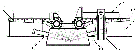
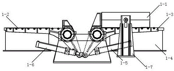
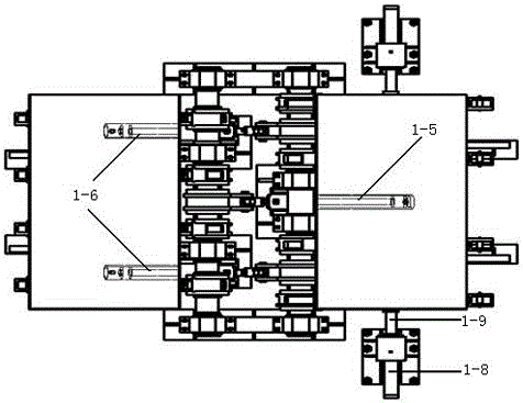
[0035] (2) Turning and alignment: place two surface-treated continuous casting slabs 1-1 with the interface to be compounded upwards, place one on the st...

Embodiment 2

[0041] Take 15CrMoRH medium-temperature hydrogen-facing steel as an example, and its carbon equivalent is >0.3%.

[0042] (1) Surface treatment: Select two continuous casting slabs of 15CrMoRH medium-temperature hydrogen-prone steel with a single billet size of 2.5m×1.5m×180mm. The processed continuous casting slab passes through a demagnetization coil with high-frequency alternating current, so that the residual magnetism of the continuous casting slab is ≤3mT, and finally the rust layer and oxide layer on the entire interface of the continuous casting slab to be compounded are removed by milling machine, so that after cleaning The height difference between the highest point and the lowest point of the continuous casting slab to be combined interface is ≤1mm, the milling depth of the side is ≥10mm, and the welding position is reserved, and the single-sided size deviation of each side of the two continuous casting slabs is ≤5mm;

[0043] (2) Turning and alignment: place two su...

Embodiment 3

[0049] Take Q345E low-alloy structural steel as an example, and its carbon equivalent is less than 0.3%.

[0050] (1) Surface treatment: Select two Q345E low-alloy structural steel continuous casting slabs with a single billet size of 3m×2m×225mm. The final continuous casting slab passes through a demagnetization coil with high-frequency alternating current to make the residual magnetism of the continuous casting slab ≤ 3mT. Finally, the milling machine is used to remove the rust layer and oxide layer on the entire interface of the continuous casting slab to be compounded, so that the cleaned The height difference between the highest point and the lowest point of the continuous casting slab to be combined interface is ≤1mm, the milling depth of the side is ≥10mm, and the welding position is reserved, and the single-sided size deviation of each side of the two continuous casting slabs is ≤5mm;

[0051] (2) Turning and alignment: place two surface-treated continuous casting slab...


PUM

PropertyMeasurementUnit
thicknessaaaaaaaaaa
thicknessaaaaaaaaaa
tensile strengthaaaaaaaaaa

Abstract

The invention belongs to the technical field of metallurgy and particularly relates to a preparation method of a super-thick alloy steel plate. The preparation method comprises steps that surface treatment is performed on two alloy steel continuous casting slabs matched in length and width dimension; the alloy steel continuous casting slabs are overlapped on a steel feeding swing arm of a tilting gear and align to each other; the alloy steel continuous casting slabs are fed into a vacuum chamber and welded through a structure with two electronic guns; when carbon equivalent of the continuous casting slabs to be compounded is smaller than 0.3%, a front electronic gun begins to perform welding from ends of the alloy steel continuous casting slabs, and a rear electronic gun begins to perform welding from middles of the alloy steel continuous casting slabs; when carbon equivalent of the continuous casting slabs to be compounded is higher than or equal to 0.3%, the distance between the two electronic guns is shortened, an electron beam of the front electronic gun is regulated into a defocusing mode, the front electronic gun preheats welding joints, and the rear electronic gun performs welding soon afterwards; heating rolling is performed on the welded slabs to obtain the super-thick alloy steel plate. By means of the technical scheme, compound interfaces between the continuous casting slabs to be compounded completely align, and yield of the super-thick alloy steel plate is increased.

Description

technical field [0001] The invention belongs to the technical field of metallurgy, in particular to a method for preparing an extra-thick alloy steel plate. Background technique [0002] After adding a certain amount of alloying elements (including one or more of chromium, nickel, molybdenum, copper, niobium, vanadium, titanium, etc.) to ordinary carbon-manganese steel, excellent high-temperature mechanical properties and high-temperature resistance can be obtained. Various alloy steels with different special properties such as oxidation performance, corrosion resistance, low temperature resistance and non-magnetic properties. At present, alloy steels are widely used in petrochemical, coal conversion, nuclear power, steam turbine cylinder, thermal power and military fields. Among them, there is a very large market gap and extremely high added value for special alloy steel plates (thickness ≥ 100mm) such as high-grade die steel and high-temperature heat-resistant steel, and c...

Claims


Application Information

Patent Timeline
Patent Type & Authority Patents(China)
IPC IPC(8): B23P15/00B23K37/04
CPCB21B1/38B21B2001/386B23K15/0013B23K15/0033B23K15/06B23P15/00
Inventor 骆宗安谢广明王光磊王国栋
Owner 沈阳科安捷材料技术有限公司
Learn More