Turning and milling compound multi-shaft power head device

A power head, turning and milling technology, applied in the direction of driving devices, large fixed members, metal processing machinery parts, etc., can solve the problem that the power shaft cannot be installed on two planes crossing, the machine tool carrier cannot be flexibly installed, and large-scale processing cannot be satisfied and other problems, to achieve the effect of small space occupation, powerful functions and large processing range

Active Publication Date: 2014-04-02
GUANGZHOU LONGBANG AUTOMATIC CONTROL EQUIP
View PDF6 Cites 23 Cited by
  • Summary
  • Abstract
  • Description
  • Claims
  • Application Information

AI Technical Summary

Problems solved by technology

[0003] 1. When the traditional CNC turning-milling compound machine tool is equipped with two-direction power heads on two vertical planes, the power shaft cannot be installed across the two planes, especially when processing large-diameter workpieces, there will be mutual interference, which cannot satisfy a wide range processing needs
[0004] 2. Due to the influence of the structure of the power head, the traditional turning-milling compound machine tool cannot be flexibly installed on the machine tool carrier, which brings inconvenience to the subsequent design and installation
[0005] 3. When the traditional CNC turning-milling compound machine tool is equipped with two-direction power heads on two vertical planes, two sets of servo motors are needed to control, which has special restrictions on the control system of the machine tool

Method used


Image

  • Turning and milling compound multi-shaft power head device
  • Turning and milling compound multi-shaft power head device
  • Turning and milling compound multi-shaft power head device

Examples


Embodiment Construction

[0034] The turning-milling composite multi-axis power head device of the present invention will be further described in detail in conjunction with the accompanying drawings:

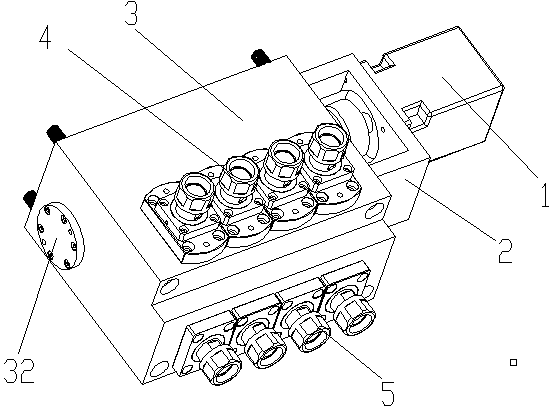
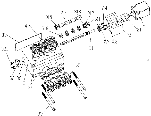
[0035] Such as Figure 1-6 Shown: a turning-milling composite multi-axis power head device according to the present invention, including a servo motor 1, a motor base 2 and a gearbox 3, the servo motor 1 is installed on the side of the motor base 2, and the motor base 2 is installed on the right side wall of the gear box 3, and two linkage shafts 21 are installed side by side in the motor base 2, and one of the linkage shafts 21 is installed on the rotating shaft of the servo motor 1; the gear box 3 A plurality of installation holes 34 are evenly provided on the two vertical surfaces, and the front axle string 4 and the side axle string 5 are respectively installed in the installation holes 34; the number of the installation holes 34 on the single vertical surface is 2 -8, and the number of correspondin...


PUM


Abstract

The invention relates to a turning and milling compound multi-shaft power head device comprising a servo motor, a motor seat and a gearbox. The servo motor is mounted on one side of the motor seat, and the motor seat is mounted on the right side wall of the gearbox. Two linkage shafts are mounted in the motor seat in parallel, and one of the linkage shafts is mounted on a revolving shaft of the servo motor. Multiple mounting holes are formed uniformly on two vertical surfaces of the gearbox, front shaft assemblies or side shaft assemblies are respectively mounted in the mounting holes. A mold cavity is reserved at the back of the gearbox, a power bearing is arranged in the mold cavity, and a bearing II, a bevel gear I, a spacer bushing, a radial locking nut, a bearing I and a frame oil-seal I are sequentially arranged on the power bearing. The turning and milling compound multi-shaft power head device has compact structure, occupies small space, and is convenient to assemble. The shaft assemblies on the two surfaces can be controlled to rotate to complete processing simultaneously. A power motor is omitted due to connection of the synchronous movement structure, and thus cost is saved.

Description

technical field [0001] The invention relates to the technical field of numerical control machine tools, in particular to a multi-axis power head device for processing turning and milling parts on a turning and milling compound numerical control machine tool. Background technique [0002] With the improvement of the processing requirements of CNC machine tools, in order to achieve complex processes such as turning, milling, drilling, tapping, and engraving in the process of processing workpieces, CNC machine tools with ordinary power heads are usually used for processing. At present, when processing workpieces with ordinary CNC turning and milling compound machine tools, there are the following deficiencies: [0003] 1. When the traditional CNC turning-milling compound machine tool is equipped with two-direction power heads on two vertical planes, the power shaft cannot be installed across the two planes, especially when processing large-diameter workpieces, there will be mu...

Claims


Application Information

Patent Timeline
Patent Type & Authority Applications(China)
IPC IPC(8): B23Q5/10B23B19/02
CPCB23Q1/70B23Q5/10
Inventor 刘芳艺谭习旺蓝方伟
Owner GUANGZHOU LONGBANG AUTOMATIC CONTROL EQUIP
Why Eureka
Try Eureka