Contactless vehicle wheel diameter dynamical measuring device and method

A non-contact, dynamic measurement technology, applied in the field of optical measurement, can solve the problems of low measurement accuracy, small operation space, complex measurement system structure, etc., and achieve the effect of simple data processing, improved response speed, and simple measurement principle.

Active Publication Date: 2014-04-02
BEIJING JIAOTONG UNIV
View PDF12 Cites 16 Cited by
  • Summary
  • Abstract
  • Description
  • Claims
  • Application Information

AI Technical Summary

Problems solved by technology

However, the instrument still uses the contact measurement method, which causes a certain amount of wear on the measuring instrument and the wheel, and the measurement point is easily affected by oil and debris on the wheel diameter.
[0006] To sum up, the existing contact measurement technology using mechanical wheel gauge generally has the following disadvantages: (1) relying on manual operation, the measurement efficiency is low, and it is not easy to find problems in time; (2) the measurement accuracy is easily affected by the external environment; (3) it must be disassembled Wheels, the measurement cycle is long; (4) Because the operating space on site is too small, this kind of contact measurement technology is generally not suitable for measuring the diameter of wheels on site
However, the existing technical solutions for non-contact dynamic measurement of wheel diameter still have the following problems to be solved: 1. The structure of the measurement system is complex and difficult to install and debug; 2. The measurement accuracy is not high; 3. The cost is expensive

Method used


Image

  • Contactless vehicle wheel diameter dynamical measuring device and method
  • Contactless vehicle wheel diameter dynamical measuring device and method
  • Contactless vehicle wheel diameter dynamical measuring device and method

Examples


Embodiment Construction

[0038] The preferred embodiments will be described in detail below in conjunction with the accompanying drawings. It should be emphasized that the following description is only exemplary and not intended to limit the scope of the invention and its application.

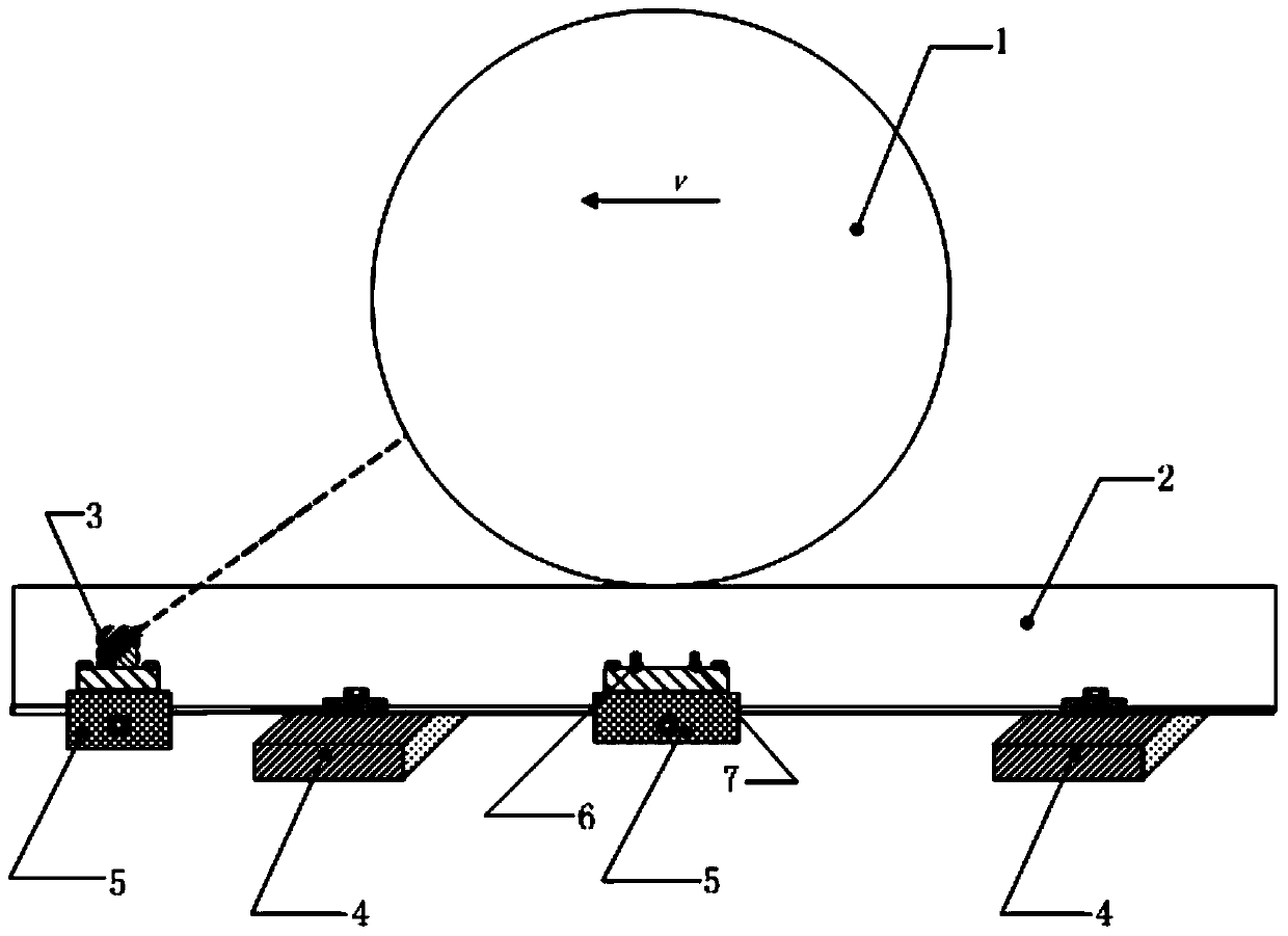
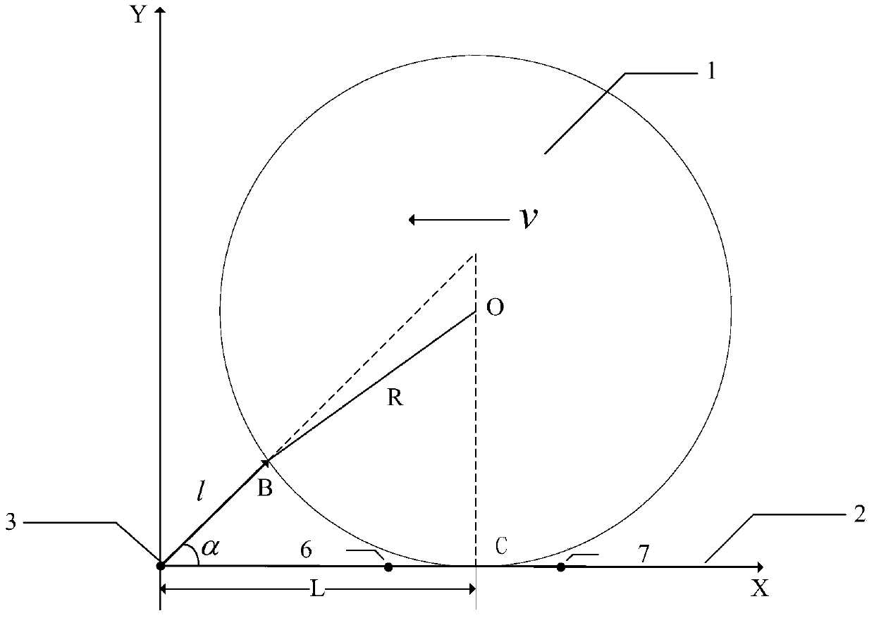
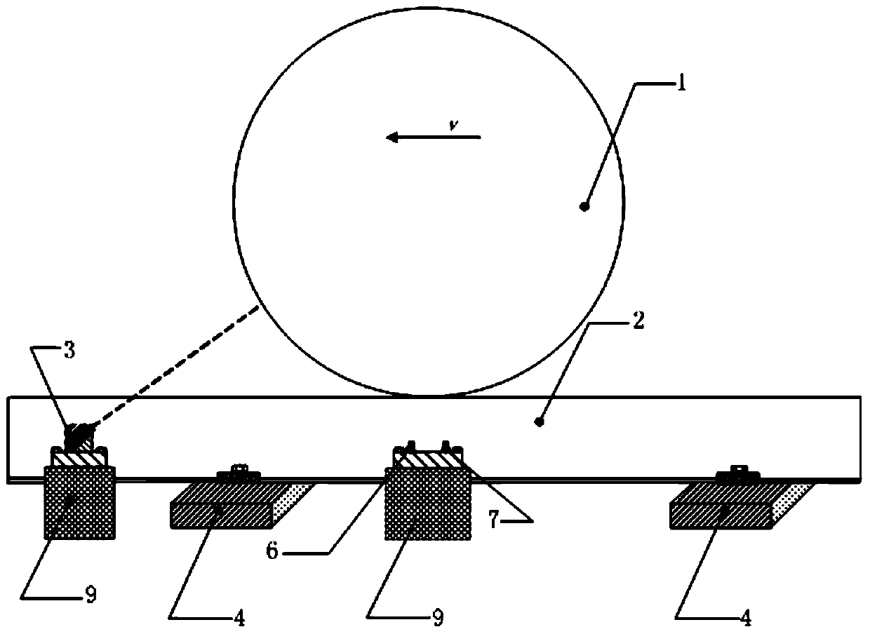
[0039] figure 1 It is the first embodiment of the non-contact dynamic measurement device for wheel diameter using a single laser displacement sensor. Such as figure 1 As shown, this embodiment is a wheel diameter non-contact dynamic measuring device using a single laser displacement sensor, specifically comprising: a laser displacement sensor 3, a first eddy current sensor 6, a second eddy current sensor 7 and a central processing unit 8 (not shown in the figure marked). The laser displacement sensor 3 , the first eddy current sensor 6 and the second vehicle eddy current sensor 7 are all fixed on the rail 2 through the block 5 or directly by bonding, and are located on the outside (or inside) of the rail 2 at the sa...


PUM


Abstract

The invention discloses a contactless vehicle wheel diameter dynamical measuring device and a contactless vehicle wheel diameter dynamical measuring method in the technical field of a contactless vehicle wheel diameter dynamical measuring. The measuring device is formed by vehicle wheel positioning units, each vehicle wheel positioning unit is composed of a laser displacement sensor and two vortex flow transducers, wherein the vehicle wheel positioning units composed of the laser displacement sensors and the vortex flow transducers are arranged along a steel rail direction. The laser displacement sensor can be used for simultaneously measuring the distances between the corresponding points on the tread of a vehicle wheel which are sensed by each sensor. Meanwhile, the vortex flow transducer can be used for detecting the distance between a vertical direction and the tread of the vehicle wheel; when the distances detected by two vortex flow transducers are same, the lowest point of the circumference of the vehicle wheel passes the middle part of the two vortex flow transducers, then the distance reading on the laser displacement sensor is recorded; thus the diameter of the vehicle wheel of a train is calculated. According to the invention, not more than three sensors are adopted, and the measuring principle is simple and practical.

Description

technical field [0001] The invention belongs to the technical field of optical measurement, and in particular relates to a non-contact wheel diameter dynamic measurement device and a measurement method thereof. Background technique [0002] With the development of my country's railway industry, the speed of trains continues to increase, which brings great convenience to people's travel, but at the same time brings great challenges to the safe operation of railways. The high-speed running of the train will intensify the wear and tear between the tread of the train wheel and the rail, resulting in changes in the diameter of the wheel, affecting the cooperation between the wheel and the track, and thus affecting the safety of the train. Therefore, after a certain period of time, the train wheels will be regularly inspected, and the wheels whose parameters exceed the limit need to be repaired or scrapped, otherwise it will bring hidden dangers to the safe operation of the train....

Claims


Application Information

Patent Timeline
Patent Type & Authority Applications(China)
IPC IPC(8): B61K9/12G01B11/10
Inventor 冯其波高岩邵双运崔建英
Owner BEIJING JIAOTONG UNIV
Why Eureka
Try Eureka