Cover sealing device for sterile filling

A technology of aseptic filling and capping, which is applied in the direction of threaded bottle caps, etc., can solve the problems of cap shavings, non-corrosion resistance, broken support rings, etc., and achieve good capping effect, convenient cleaning and comprehensive disinfection

Active Publication Date: 2014-04-02
ZHANGJIAGANG BEIER MACHINERY
View PDF7 Cites 8 Cited by
  • Summary
  • Abstract
  • Description
  • Claims
  • Application Information

AI Technical Summary

Problems solved by technology

The capping head device currently used in aseptic filling production includes an adjustment ring. A capping mold is arranged at the lower end of the adjustment ring, and a driving device that can drive the capping mold to move up and down is arranged at the upper end of the adjustment ring. There are two clamping rings, in which there are several positive and negative magnets placed respectively. The distance between the two clamping rings is used to control the magnitude of the torque generated during capping. The closer the distance between the two clamping rings, the greater the torque generated under the action of the magnetic field; It rotates under the action of the driving device and moves downward under the action of the driving device. When the bottle cap is pressed against the mouth of the beverage bottle with a support ring, the capping work begins. When the bottle cap is screwed on the beverage bottle, the two clips The torque generated between the tight rings is not enough to drive the bottle cap to continue to rotate. At this time, there will be slippage between the capping mold and the bottle cap, which will cause shavings on the outer surface of the bottle cap, and even worse, the The support ring is broken; in addition, this device mainly relies on the magnetic field between the magnets to generate torque. The magnet is a vulnerable part, easy to wear and not resistant to corrosion, which will inevitably affect the sealing performance of the bottle cap on the capped beverage bottle

Method used


Image

  • Cover sealing device for sterile filling
  • Cover sealing device for sterile filling
  • Cover sealing device for sterile filling

Examples


Embodiment Construction

[0014] The technical solutions of the present invention will be further described in detail below in conjunction with the accompanying drawings and preferred embodiments.

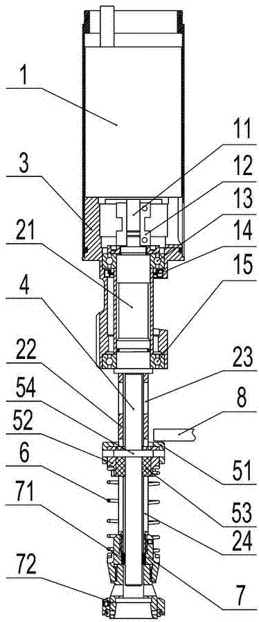
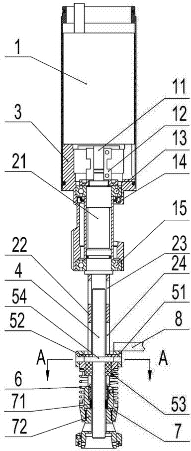
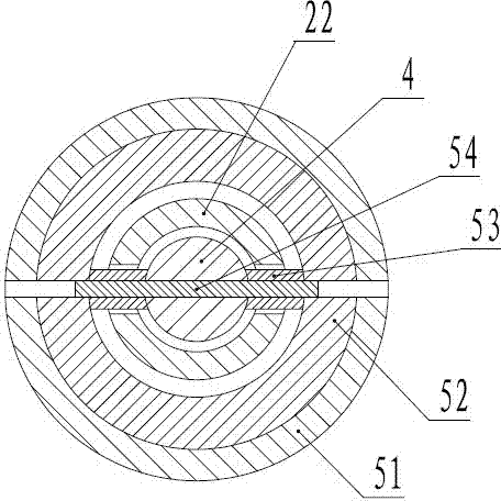
[0015] like figure 1 , figure 2 , image 3 As shown, the capping head device for aseptic filling described in this embodiment includes a main shaft, and a driving device is arranged on the upper end of the main shaft, and the driving device can drive the main shaft to rotate; the upper part of the main shaft is a solid shaft 21, and the lower part is The hollow shaft 22 is provided with a bottle cap ejecting rod 4 inside the hollow shaft 22. The bottle cap ejecting rod 4 can move up and down in the hollow shaft 22. A guide groove 24 is respectively arranged on both sides of the hollow shaft 22. The upper cover is equipped with a sliding device, which is fixedly connected with the bottle cap ejecting rod 4 through the guide groove 24, and the lower end of the hollow shaft 22 is also fixedly installed with...


PUM


Abstract

The invention discloses a cover sealing device for sterile filling, which comprises a spindle, wherein a driving device is arranged at the upper end of the spindle; the driving device can drive the spindle to rotate; a solid shaft is arranged on the upper part of the spindle; a hollow shaft is arranged on the lower part of the spindle; a bottle cover pushing rod is arranged in the hollow shaft; the bottle cover pushing rod can move up and down in the hollow shaft; guiding slots are respectively arranged on the two sides of the hollow shaft; a sliding device is sleeved on the hollow shaft; the sliding device is fixedly connected with the bottle cover pushing rod through the guiding slots; a cover sealing mould base is fixedly mounted at the lower end of the hollow shaft; the cover sealing mould base is clamped with a cover sealing mould; a guiding spring is sleeved on the hollow shaft; the two ends of the guiding spring are respectively supported against the sliding device and the cover sealing mould base; under the action of the guiding spring, the sliding device can drive the bottle cover pushing rod to upward move relative to the cover sealing mould base. The cover sealing device for sterile filling has the advantages of convenience in cleaning and disinfecting, no oil stain pollution and good cover sealing effect.

Description

technical field [0001] The invention relates to a capping machine, in particular to a capping head device for aseptic filling of beverages in the capping machine. Background technique [0002] With the development of the market economy, the beverage industry has gradually become a fast-growing industry. At present, the beverages sold on the market have gradually tended to be low-carbon, low-alcohol and low-sugar. Beverages with low sugar characteristics are called neutral beverages. As we all know, neutral beverages cannot be filled by hot filling. The filling of neutral beverages is mainly aseptic filling. Among them, the capping head device is A major component of aseptic filling equipment. The capping head device currently used in aseptic filling production includes an adjustment ring. A capping mold is arranged at the lower end of the adjustment ring, and a driving device that can drive the capping mold to move up and down is arranged at the upper end of the adjustment...

Claims


Application Information

Patent Timeline
Patent Type & Authority Applications(China)
IPC IPC(8): B67B3/20
Inventor 黄振华唐志华袁丽芳
Owner ZHANGJIAGANG BEIER MACHINERY
Why Eureka
Try Eureka