
Circumference cutting machine

A cutting machine and circle technology, applied in the direction of roads, road repairs, roads, etc., can solve the problems of difficulty in moving the circular cutting machine, difficulty in ensuring the accuracy of the cutting depth value, lack of mechanical self-energy control, etc., to achieve simple structure, Simple and convenient adjustment, strong overall effect

Inactive Publication Date: 2014-04-02
GUANGDONG ESUN HEAVY IND CO LTD
View PDF5 Cites 7 Cited by
  • Summary
  • Abstract
  • Description
  • Claims
  • Application Information

AI Technical Summary

Problems solved by technology

This kind of circular cutting machine has the following disadvantages: (1) The mechanism for realizing circular cutting movement is relatively complicated, and lacks mechanical self-energy control, which is difficult to control and has low work efficiency; (2) The mechanism for realizing cutting radius adjustment is poor in stability , the adjustment is more troublesome; (3) The mechanism for adjusting the cutting depth is poor in stability, lacks mechanical self-energy control, and the work efficiency is low. Manual adjustment of the cutting depth is used, and the adjusted cutting depth value is difficult to guarantee its accuracy; (4) The It is very difficult to carry and move the circular cutting machine, and it requires a lot of labor to carry it. When the position needs to be adjusted during the construction process, workers must be used to lift the whole machine and move it. The adjustment process is very cumbersome

Method used


Image

  • Circumference cutting machine
  • Circumference cutting machine
  • Circumference cutting machine

Examples


Embodiment Construction

[0055] The present invention will be further described in detail below in conjunction with the accompanying drawings and specific embodiments.

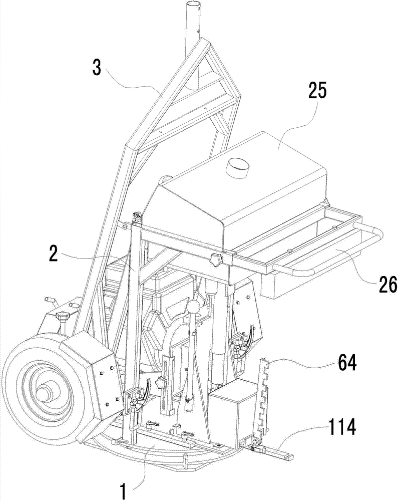
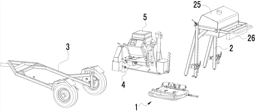
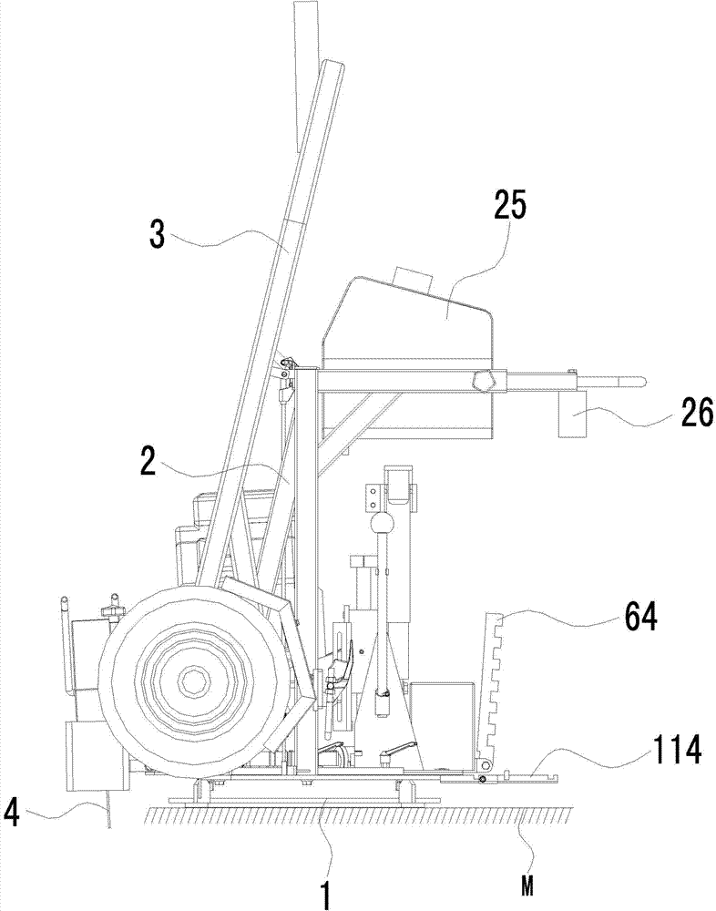
[0056] like Figure 1 to Figure 28 As shown, a circumferential cutting machine includes a base 1 and a cutting machine body installed on the base 1, the cutting machine body includes a cutting piece 4 and a power unit 5 that drives the cutting piece 4 to rotate;

[0057] The base 1 includes an upper movable assembly 11 and a lower fixed assembly 12 that can be fixed on the ground or a manhole cover. A slewing bearing is provided between the upper movable assembly 11 and the lower fixed assembly 12, and the outer ring 131 of the slewing bearing is fixed to the lower fixed assembly 12. Connection, the inner ring 132 of the slewing bearing is fixedly connected with the upper movable assembly 11, the outer wall of the outer ring 131 of the slewing bearing has circumferentially distributed teeth, and the upper movable assembly 11 is equipp...


PUM


Abstract

The invention relates to a circumference cutting machine. The circumference cutting machine comprises a base and a cutting machine body which is installed on the base, wherein the cutting machine body comprises a cutting blade and a power device, the base comprises an upper movable assembly and a lower fixed assembly which can be fixed on the ground or a well lid, a rotary bearing is also arranged between the upper movable assembly and the lower fixed assembly, and the upper movable assembly is provided with a rotary driving mechanism; the cutting machine body also comprises a horizontal slide plate, the horizontal slide plate is fixedly provided with a supporting frame, the supporting frame is provided with an elevation guide rail, an elevation frame is installed on the elevation guide rail, an elevation driving device is arranged between the supporting frame and the elevation frame, the cutting blade and the power device are installed on the elevation frame, and the upper movable assembly is provided with a plate locking mechanism which is used for selectively allowing or preventing the horizontal slide of the horizontal slide plate. The circumference cutting machine is simple in structure, high in mechanical degree, precise to control, high in working efficiency, simple and convenient to adjust, large in application range, strong in integrity and small in size.

Description

technical field [0001] The invention relates to a circular cutting machine, in particular to a circular cutting machine for adding wells on the road surface and repairing existing wells. Background technique [0002] After the asphalt road is used for a period of time, the road surface will be damaged one after another, especially when many types of manhole covers are installed on the road, there will be pits, cracks, cracks, etc. on the road around the manhole cover, which need to be partially repaired. Traditional methods of repairing existing manhole covers include cutting, excavating, and then filling with new material. However, the traditional cutting machine first cuts the road surface in a straight line, and then adjusts the direction of the cutting machine to cut roughly in a quadrangular shape. In this method, the operator cuts the cutting part into a quadrangular shape, and the shape of the round manhole does not match the cutting part. It not only brings inconven...

Claims


Application Information

Patent Timeline
IPC IPC(8): E01C23/09
Inventor 贾永力邹慧娟杨刚黄开金薛浩帅李熙吴土祥
Owner GUANGDONG ESUN HEAVY IND CO LTD
Learn More