Check patentability & draft patents in minutes with Patsnap Eureka AI!

A parallel flow heat exchanger

A parallel flow heat exchanger, a pair of technology, applied in the direction of heat exchanger shell, indirect heat exchanger, heat exchanger type, etc., can solve the problem of difficulty in reducing production cost, easy to produce waste, affecting the heat exchange efficiency of working fluid, etc. question

Active Publication Date: 2016-02-10
浙江新金宸机械有限公司
View PDF8 Cites 0 Cited by
  • Summary
  • Abstract
  • Description
  • Claims
  • Application Information

AI Technical Summary

Problems solved by technology

These improved structures can play the role of evenly distributing the medium, but the structure is still very complicated, the fluidity of the medium is not good, which affects the heat exchange efficiency of the working fluid, and the header also has high requirements for production technology, and it is easy to produce waste products , making it difficult to reduce production costs, which is not conducive to the promotion and application of products

Method used


Image

  • A parallel flow heat exchanger

Examples


Embodiment

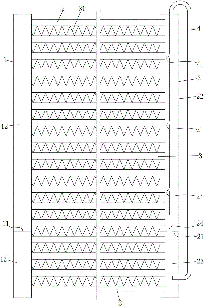
[0011] Example: see figure 1 , the present invention includes a pair of left and right headers that are parallel to each other and separated from each other and several flat tubes whose two ends are respectively communicated with the inner chambers of the left and right headers and are parallel to each other. Fins are arranged between adjacent flat tubes, wherein the left collector There is a left partition in the manifold to separate the left manifold into the upper chamber of the left manifold and the lower chamber of the left manifold, and a right partition is arranged in the right manifold to divide the right manifold into the right manifold The upper chamber and the lower chamber of the right collector, the upper chamber of the right collector and the lower chamber of the right collector are connected through the through hole on the right partition, the upper chamber of the left collector and the right collector The height of the upper chamber is equal, the height of the ...


PUM


Abstract

The invention relates to a parallel flow heat exchanger with a novel structure. Left and right separators are arranged in left and right collecting pipes to divide the left and right collecting pipes into left and right collecting pipe upper cavities and left and right collecting pipe lower cavities. The right collecting pipe upper cavity is communicated with the right collecting pipe lower cavity by a through hole in the right separator, wherein the heights of the left collecting pipe upper and lower cavities are respectively equal to those of the right collecting pipe upper and lower cavities; the heights of the left and right collecting pipe upper cavities are greater than those of the left and right collecting pipe lower cavities; the right collecting pipe is also provided with a U-shaped communicating pipe; a pipe orifice of a vertical pipe at one side of the communicating pipe is sealed, the vertical pipe at one side of the communicating pipe extends into the right collecting pipe upper cavity from the upper end port of the right collecting pipe, and the pipe wall of the vertical pipe at one side of the communicating pipe is provided with a plurality of openings; a pipe orifice of a vertical pipe at the other side of the communicating pipe is open and the vertical pipe at the other side of the communicating pipe extends to pass through the pipe wall of the right collecting pipe to enter the right collecting pipe lower cavity. According to the invention, liquidity of a working medium is improved; heat exchange efficiency of the working medium is greatly improved; a structure and a production process of the collecting pipe are simplified; the requirement on the production technology is reduced; the rejection rate is reduced; the production cost is reduced.

Description

technical field [0001] The invention belongs to the technical field of parallel flow heat exchangers, in particular to a parallel flow heat exchanger. Background technique [0002] Parallel flow heat exchanger is a device that realizes heat transfer between hot and cold fluids, and is widely used in HVAC and other fields. Parallel flow heat exchangers generally include two headers parallel to each other, a number of substantially parallel flat tubes for heat dissipation are arranged between the two headers, and fins for heat dissipation are brazed between adjacent flat tubes. When working, the medium flows along the flat tubes between the headers in the design direction, and exchanges heat with the air blowing through the fins while flowing. In order to improve the heat exchange efficiency, the medium must be evenly distributed and flow through each cooling flat tube, which requires improvement in the structure of the header. The applicant's patent "parallel flow heat exch...

Claims


Application Information

Patent Timeline
Patent Type & Authority Patents(China)
IPC IPC(8): F25B39/00F28D7/16F28F9/02
Inventor 董长盛
Owner 浙江新金宸机械有限公司
Features
  • R&D
  • Intellectual Property
  • Life Sciences
  • Materials
  • Tech Scout
  • Unparalleled Data Quality
  • Higher Quality Content
  • 60% Fewer Hallucinations
Learn More