
Transducer for detecting rock mass acoustic wave

A technology of acoustic wave detection and transducer, which is applied in the direction of instruments, using sound waves/ultrasonic waves/infrasonic waves to analyze solids, and using sound waves/ultrasonic waves/infrasonic waves for material analysis, etc., to achieve the effect of ensuring consistency and coupling conditions

Inactive Publication Date: 2014-04-02
WUHAN UNIV
View PDF8 Cites 7 Cited by
  • Summary
  • Abstract
  • Description
  • Claims
  • Application Information

AI Technical Summary

Problems solved by technology

[0005] The purpose of the present invention is exactly according to the situation of above-mentioned prior art, aiming at the sound wave detection of rock mass excavation and blasting influence scope, proposes a kind of rock mass sound wave detection transducer, to solve the problem caused by using water as coupling agent in sound wave detection. problems, and at the same time make up for the shortcomings of using the existing dry hole transducer detection method

Method used


Image

  • Transducer for detecting rock mass acoustic wave
  • Transducer for detecting rock mass acoustic wave
  • Transducer for detecting rock mass acoustic wave

Examples


Embodiment 1

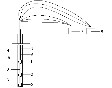
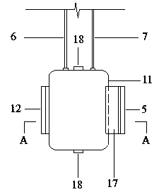
[0025] Below in conjunction with accompanying drawing, the present invention is further described: as figure 1 , Figure 3-6 As shown, a rock mass acoustic wave detection transducer includes a transmitting transducer 1, a receiving transducer 2, a rigid connecting pipe 3, a measuring rod 4, a hydraulic pump 8 and an acoustic wave collection device 9, and the transmitting transducer 1 is connected to the receiving transducer 2 through a rigid connecting pipe 3, the top of the transmitting transducer 1 is connected to the measuring rod 4, and the transmitting transducer 1 is connected to the hydraulic pump 8 and the sound wave collection device 9 through pipelines; the transmitting transducer 1 The device 1 and the receiving transducer 2 are dry-hole transducers with built-in piezoelectric ceramics 13, hydraulic contacts 12 and hydraulic rigid pads 5. The piezoelectric ceramics 13 in the transmitting transducer 1 emit sound waves, and the piezoelectric ceramics 13 in the receiv...

Embodiment 2

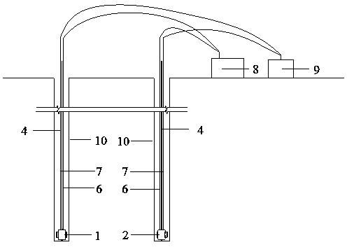
[0038] Below in conjunction with accompanying drawing, the present invention is further described: as Figure 2-6 As shown, a rock mass acoustic wave detection transducer includes a transmitting transducer 1, a receiving transducer 2, a measuring rod 4, a hydraulic pump 8 and an acoustic wave acquisition device 9; the transmitting transducer 1 is located at another acoustic The tops of the receiving transducers 2 in the wave detection hole 10 are respectively connected with measuring rods 4, and the transmitting transducers 1 are respectively connected with the hydraulic pump 8 and the sound wave collection equipment 9 through pipelines, and the receiving transducers located in the other sound wave detection hole 10 The transducer 2 is connected to the hydraulic pump 8 and the sound wave collection device 9 respectively through pipelines; the transmitting transducer 1 and the receiving transducer 2 are dry-hole transducers with built-in piezoelectric ceramics 13, hydraulic cont...


PUM

PropertyMeasurementUnit
pore sizeaaaaaaaaaa
lengthaaaaaaaaaa
lengthaaaaaaaaaa

Abstract

The invention discloses a transducer for detecting a rock mass acoustic wave. The transducer comprises a transmitting transducer (1), a receiving transducer (2), a rigid connection pipe (3), a measuring bar (4), a hydraulic pump (8) and an acoustic wave collecting device (9), wherein the transmitting transducer (1) is connected with the receiving transducer (2) through the rigid connection pipe (3); the top end of the transmitting transducer (1) is connected with the measuring bar (4). The transducer has the advantages that dry hole detection of an acoustic wave test is achieved under the condition that a coupling agent does not need to be introduced through direct contact of a scalable hydraulic contact and hole wall rock mass of a detection hole; the transducer is not affected by water supply for construction, and drilling azimuth and angle, and can adapt to various detection conditions on the scene; the coupling pressure is controlled through hydraulic equipment with a pressure gage, and the consistence of the coupling conditions can be ensured. The effect of the coupling agent is removed, and the consistence of the coupling conditions is ensured, so that the data in the aspects of acoustic wave amplitude, frequency spectrum and the like also can be obtained besides the condition that the waveform jump point can be accurately judged to obtain acoustic wave velocity data in the acoustic wave test by using the device provided by the invention.

Description

technical field [0001] The invention relates to the technical fields of water conservancy and hydropower and geotechnical engineering, in particular to a rock mass acoustic wave detection transducer for determining the impact range of rock mass excavation and blasting. Background technique [0002] During the blasting and excavation of rock mass, due to the effect of blast load, dynamic damage to the retained rock mass will inevitably occur while the rock blasting is completed; at the same time, with the formation of a new free surface, the physical and mechanical properties of the rock mass will be preserved. Disturbance and deterioration occur, forming so-called excavation disturbance zones or excavation damage zones. The excavation disturbance area or excavation damage area will have adverse effects on the safety of the preserved rock mass and engineering buildings. Reasonably and accurately judging the impact range of rock mass excavation and blasting, and judging the e...

Claims


Application Information

Patent Timeline
Patent Type & Authority Applications(China)
IPC IPC(8): G01N29/04G01N29/22
CPCG01N29/043G01N29/07G01N29/28G01N2291/0232G01N2291/048G01N2291/103
Inventor 卢文波张玉柱严鹏陈明周创兵
Owner WUHAN UNIV
Learn More