Infrared/visible dual-waveband photoelectric self-aligning system

A photoelectric self-collimation, dual-band technology, applied in the optical field, can solve single problems, and achieve the effect of expanding the use range, effective use range, and easy miniaturization design.

Active Publication Date: 2014-04-02
XI'AN INST OF OPTICS & FINE MECHANICS - CHINESE ACAD OF SCI
View PDF6 Cites 4 Cited by
  • Summary
  • Abstract
  • Description
  • Claims
  • Application Information

AI Technical Summary

Problems solved by technology

[0003] In order to solve the technical problem that the existing self-collimation optical system can only use a single-band light for testing, the present invention provides an infrared / visible dual-band photoelectric self-collimation system

Method used


Image

  • Infrared/visible dual-waveband photoelectric self-aligning system
  • Infrared/visible dual-waveband photoelectric self-aligning system
  • Infrared/visible dual-waveband photoelectric self-aligning system

Examples


Embodiment Construction

[0025] The present invention will be further described below in conjunction with the accompanying drawings.

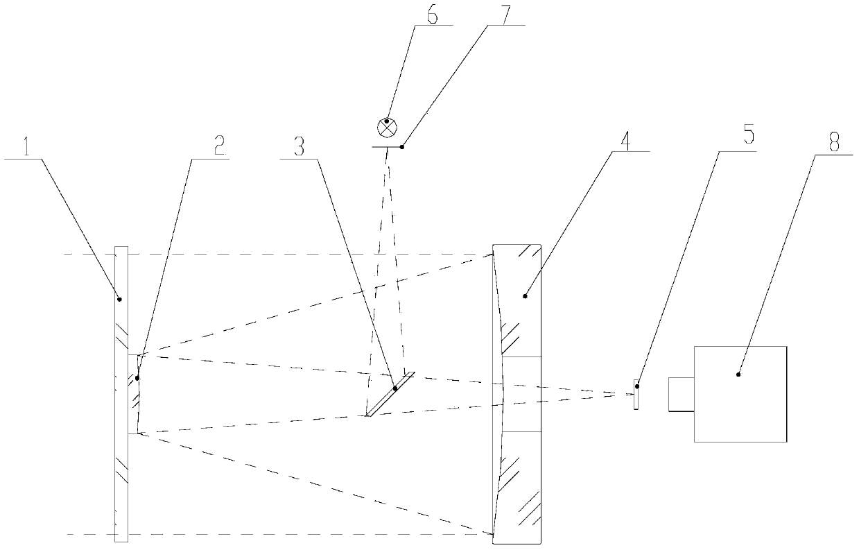
[0026] Such as figure 1 As shown, an infrared / visible dual-band photoelectric self-collimation system includes a light source 6, a beam splitter 3, a secondary mirror 2, a protective window 1, a primary mirror 4 and a reading imaging device, and the beam splitter 3 is located on the radiation light path of the light source 6 , the secondary mirror 2 is located on the reflection light path of the beam splitter 3, the protective window 1 is used to fix the secondary mirror 2, the primary mirror 4 is located on the reflection light path of the secondary mirror 2, the primary mirror 4 reflects a parallel light beam, and the reading imaging device 5 is arranged on the beam splitter The transmitted light path of mirror 3.

[0027] The special feature of the present invention is that the primary mirror 4 is a paraboloid, and the secondary mirror 2 is a hyperboloid RC structu...


PUM


Abstract

The invention provides an infrared/visible dual-waveband photoelectric self-aligning system, which comprises a light source, a beam splitter, a secondary lens, a protection window, a main lens and a reading imaging device, wherein the beam splitter is positioned on the radiation light path of the light source; the secondary lens is positioned on the reflecting light path of the beam splitter; the protection window is used for fixing the secondary lens; the main lens is positioned on the reflecting light path of the secondary lens; the main lens is used for reflecting parallel beams; the reading imaging device is arranged on the transmitting light path of the beam splitter; the reflecting surface of the main lens is a paraboloid; the secondary lens has a hyperboloid structure. By adopting the infrared/visible dual-waveband photoelectric self-aligning system, the requirement of visible and infrared parallel light source testing can be met. The infrared/visible dual-waveband photoelectric self-aligning system can be used as an infrared/visible parallel light tube as well as an infrared/visible light self-aligning system.

Description

technical field [0001] The invention belongs to the field of optics and relates to an autocollimation system. Background technique [0002] The traditional autocollimation optical system is an autocollimation system with a single working band, which projects an image of a reticle in the form of a parallel beam (collimated light) onto a mirror (object under test), which is object) reflects its beam back to the autocollimator. This is the autocollimated image. If the mirror (object under test) is perpendicular to the optical axis, the beam will reflect back on itself; if the mirror (object under test) is tilted at an angle, its reflected light will reflect back at an angle. Depending on how tilted the reflected light is, the autocollimated image is displaced by a larger or smaller angle. The angle change of the mirror (object under test) can be measured by measuring the displacement of the self-collimation image on the X-axis and Y-axis. Generally, the system can only comp...

Claims


Application Information

Patent Timeline
Patent Type & Authority Applications(China)
IPC IPC(8): G02B27/30G02B27/10
Inventor 曹焱王苗郝伟
Owner XI'AN INST OF OPTICS & FINE MECHANICS - CHINESE ACAD OF SCI
Why Eureka
Try Eureka