Antenna and wireless signal transmit-receive system

An antenna and signal source technology, applied in the field of antennas and wireless signal transceiver systems, can solve problems such as poor uniformity of radiated signals

Inactive Publication Date: 2015-04-29
XIAN RUIXIN TECH CO LTD
View PDF5 Cites 12 Cited by
  • Summary
  • Abstract
  • Description
  • Claims
  • Application Information

AI Technical Summary

Problems solved by technology

To solve the problem of poor uniformity of

Method used


Image

  • Antenna and wireless signal transmit-receive system
  • Antenna and wireless signal transmit-receive system
  • Antenna and wireless signal transmit-receive system

Examples


Embodiment Construction

[0054] The following will clearly and completely describe the technical solutions in the embodiments of the present invention with reference to the accompanying drawings in the embodiments of the present invention. Obviously, the described embodiments are only some, not all, embodiments of the present invention. Based on the embodiments of the present invention, all other embodiments obtained by persons of ordinary skill in the art without creative efforts fall within the protection scope of the present invention.

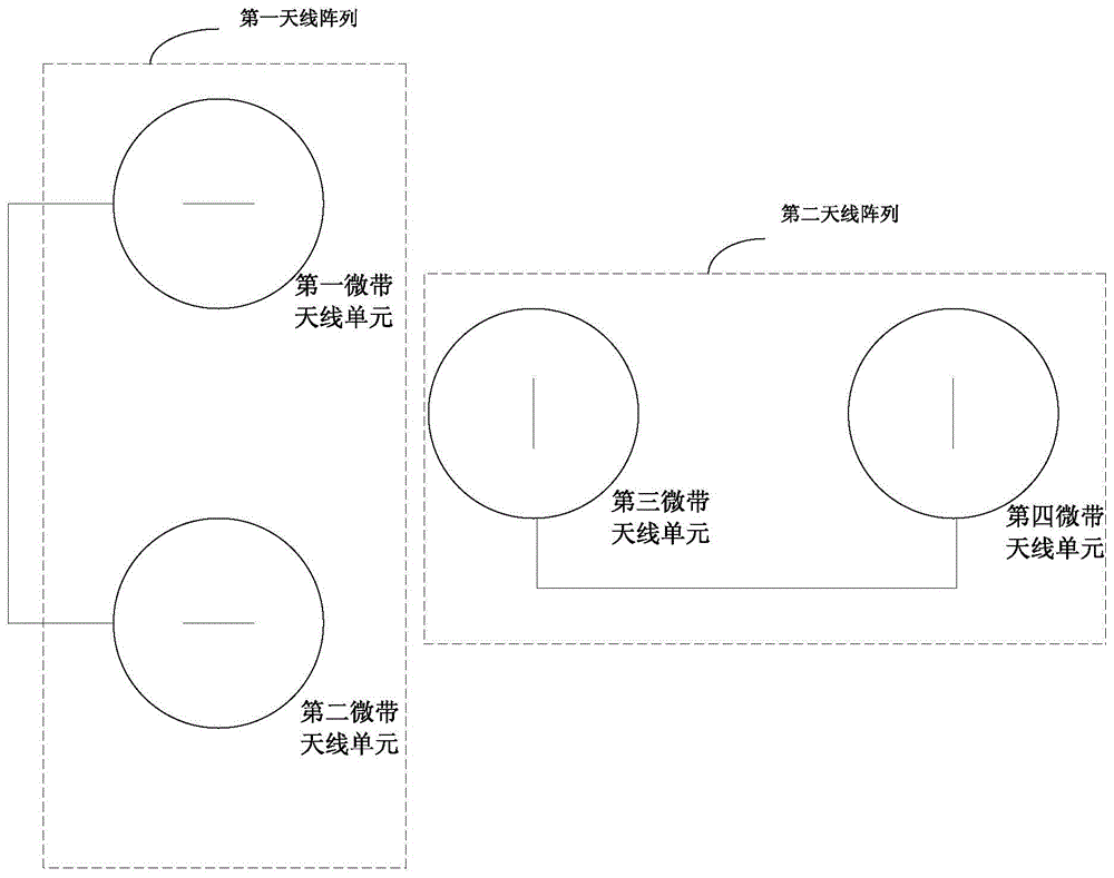
[0055] Please refer to figure 1 , is a schematic composition diagram of the first embodiment of the antenna of the present invention, and optionally, the antenna is an indoor ceiling antenna. Of course, in addition to the commonly used indoor ceiling installation scenario, the antenna in the embodiment of the present invention can also be used in other scenarios such as open outdoors, for example, the antenna can be supported by a high pole.

[0056] In this embod...


PUM

PropertyMeasurementUnit
Angleaaaaaaaaaa

Abstract

The embodiment of the invention discloses an antenna which comprises two antenna arrays. Each antenna array comprises two microstrip antenna units, the feed magnitudes of every two microstrip antenna units are equal, the feed phase difference between the every two microstrip antenna units is 180 degrees, the work frequencies of every two microstrip antenna units are the same, and the distance between the centers of every two microstrip antenna units ranges from 0.5 wave length to 1 wave length of the center frequency of a work frequency band of any one microstrip antenna unit. The included angle between the two antenna arrays ranges from 30 to 150 degrees in the same plane, and the distance between the middle point of the distance between the centers of the two microstrip antenna units of the first antenna array and the middle point of the distance between the centers of the two microstrip antenna units of the second antenna array is smaller than or equal to 3 wave lengths of the center frequency of the work frequency band of the microstrip antenna unit with the shortest wave length. The embodiment of the invention further discloses a wireless signal transmit-receive system. By means of the antenna and the wireless signal transmit-receive system, the uniformity of antenna radiation signals can be improved, and the blind area of radiation coverage is reduced.

Description

technical field [0001] The invention relates to the technical field of communication, in particular to an antenna and a wireless signal transceiving system. Background technique [0002] For indoor coverage scenarios of mobile communications, the most commonly used antenna installation method is ceiling installation, that is, installing the antenna on the ceiling. [0003] In the prior art, a dish cone antenna is usually used for ceiling installation. The end-fire array in the dish cone antenna is horizontally polarized. By cooperating with other vertically polarized antenna elements, it can meet the requirements of the ceiling antenna with low radiation in the normal direction and high radiation in the horizontal direction. refers to the radiation direction of the antenna, and the horizontal direction is perpendicular to the normal direction of the antenna. In order to expand the radiation range of the antenna in the horizontal direction, it is necessary to increase the t...

Claims


Application Information

Patent Timeline
IPC IPC(8): H01Q21/29H01Q21/00
Inventor 罗兵石中立覃雯斐
Owner XIAN RUIXIN TECH CO LTD
Why Eureka
Try Eureka