

Laminator and lamination method thereof
A stacking machine and stacking technology, which is applied in battery assembly machines, sustainable manufacturing/processing, electrochemical generators, etc., can solve problems such as difficult efficiency breakthroughs, and improve production efficiency, production quality, and stacking speed Improved effect
- Summary
- Abstract
- Description
- Claims
- Application Information
AI Technical Summary
Problems solved by technology
Method used
Image

Examples
Embodiment 1
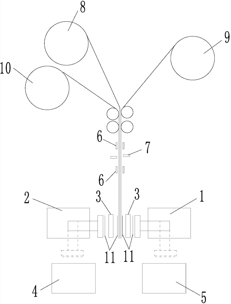
[0075] In order to solve the production efficiency problem of the existing stacking machine, Embodiment 1 of the present invention provides a stacking machine for stacking lithium-ion batteries. Such as figure 1 As shown, the laminate machine includes a first rotary manipulator 1 , a second rotary manipulator 2 , a primary positioning platform 5 , a secondary positioning platform 4 and a first clamping knife 3 . At the upper or lower ends of the first rotary manipulator 1 and the second rotary manipulator 2, there are installation devices (not shown) for the negative electrode sheet 8, the first diaphragm 9 and the second diaphragm 10. The installation device can be a mounting roller or other Similarly, the installation devices of the first diaphragm 9 and the second diaphragm 10 are respectively arranged on both sides of the installation device of the negative electrode sheet 8, and the first diaphragm 9, the negative electrode sheet 8 and the second diaphragm 10 are sequenti...
Embodiment 2
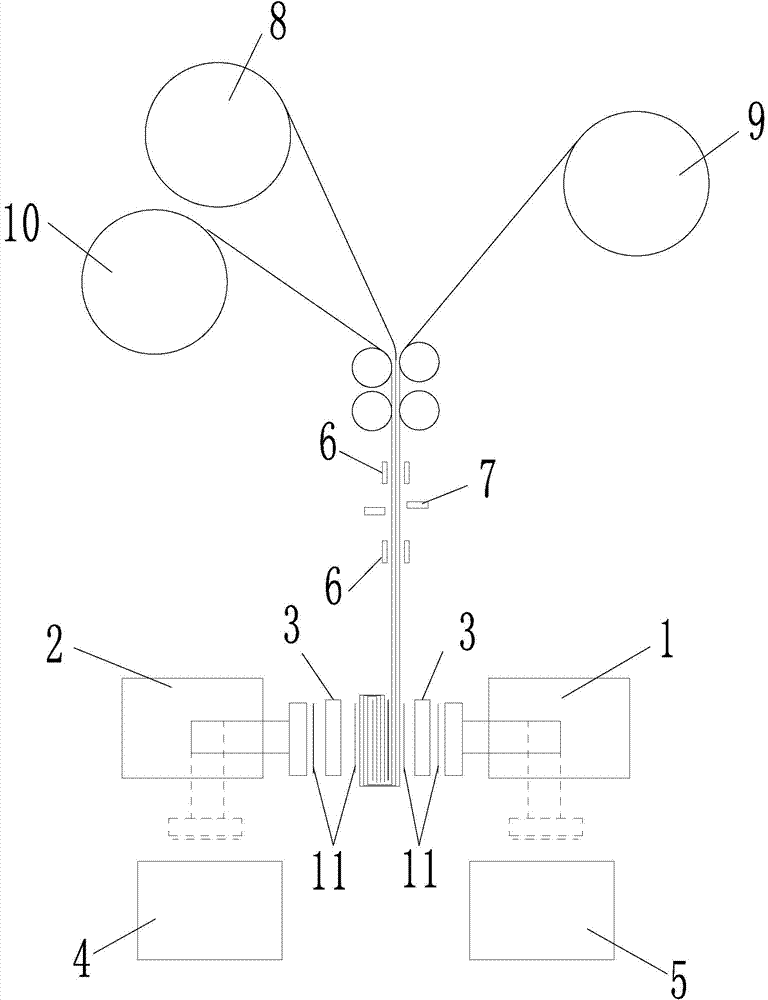
[0090] The difference between this embodiment and Embodiment 1 is that this embodiment is a single stack, that is, the positive electrode sheet is sucked on one side of the separator, and the stack is wound by rotating 180 degrees. The present embodiment is described in detail below in conjunction with accompanying drawing:
[0091] In order to solve the production efficiency problem of the existing stacking machine, Embodiment 2 of the present invention provides a stacking machine for stacking lithium-ion batteries. Such as Figure 5 As shown, the laminate machine includes a first rotary manipulator 1 , a primary positioning table 5 and a first clamping knife 3 . At the upper or lower ends of the first rotary manipulator 1 and the second rotary manipulator 2, there are installation devices (not shown) for the negative electrode sheet 8, the first diaphragm 9 and the second diaphragm 10. The installation device can be a mounting roller or other Similarly, the installation de...
Embodiment 3
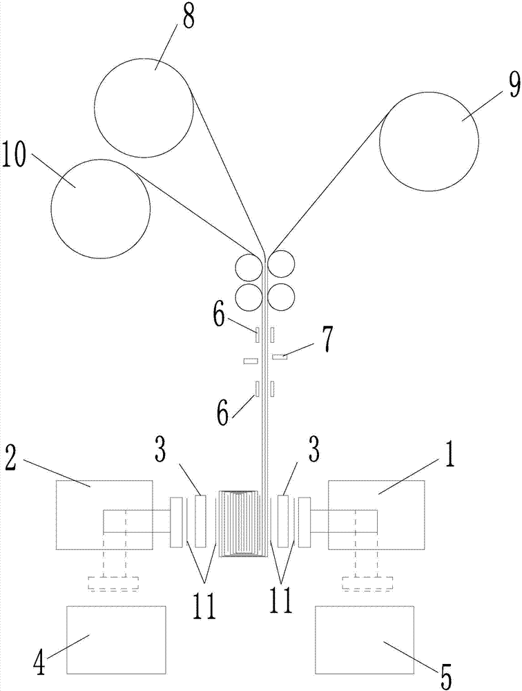
[0106] The difference between this embodiment and embodiment 2 is that in embodiment 2, the positive electrode sheet is sucked on the first diaphragm side, and the stack is wound counterclockwise by 180 degrees; in this embodiment, the positive electrode sheet is sucked on the second diaphragm side, Rotate the lamination 180 degrees clockwise. The present embodiment is described in detail below in conjunction with accompanying drawing:
[0107] In order to solve the production efficiency problem of the existing stacking machine, Embodiment 3 of the present invention provides a stacking machine for stacking lithium-ion batteries. Such as Figure 10As shown, the laminate machine includes a second rotary manipulator 2 , a second positioning table 4 and a first clamping knife 3 . At the upper or lower ends of the first rotary manipulator 1 and the second rotary manipulator 2, there are installation devices (not shown) for the negative electrode sheet 8, the first diaphragm 9 and...
PUM
 Abstract
Description
Claims
Application Information