Signal time delay stable transmission method and system of broadband

A signal and stable technology, applied in the field of signal transmission, can solve problems such as complex system structure, and achieve the effect of simple system structure, large compensation range and large bandwidth

Inactive Publication Date: 2014-04-02
BEIJING UNIV OF POSTS & TELECOMM
2 Cites 18 Cited by

AI-Extracted Technical Summary

Problems solved by technology

[0006] The present invention provides a broadband signal time-delay stable transmission method and system to solve the technical problems in the prior ...

Method used

In the broadband signal delay stable transmission method and system that the embodiment of the present invention proposes, by comparing the phase difference of the return radio frequency signal and the radio frequency standard signal transmitted back and forth, the time delay jitter of the optical fiber link is obtained, Then the tunable laser is used to change the laser wavelength, and the jitter is compensated by the different dispersion delays generated when different wavelengths are transmitted in the optical fiber, and finally the radio frequency signal output with stable frequency and phase at the far end is realized. In the embodiment of the present invention, the optical fiber is used as the transmission medium and the compensation device at the same time, and no additional compensation device is needed to realize the phase shake compensation process. The system structure is simple and the practicability is strong.
It can be see...

Abstract

The invention provides a signal time delay stable transmission method and system of broadband. The method comprises the steps of producing stable frequency standard signals in a center station, producing light carrier through a tunable laser, modulating the frequency standard signals onto the light carrier, so as to form initial light signals, transmitting the light signals to a remote terminal through an optical fiber, transmitting the light signals of the remote terminal back to the identical optical fiber to the center station, demodulating the light signals which are transmitted back, comparing return radio-frequency signals and the frequency standard signals, so as to obtain a phase difference, controlling the tunable laser to change the length of the light carrier according to the phase difference, so as to obtain compensation light carrier and ensure that the sum of a chromatic dispersion time delay inequality and a link time delay variation is zero, inputting broadband radio-frequency signals from the remote terminal, modulating the broadband radio-frequency signals input by the remote terminal onto the light signals of the remote terminal, so as to form remote modulating light signals, transmitting the remote modulating light signals back, demodulating the remote modulating light signals received by the center station into stable remote terminal radio-frequency signals, and outputting the stable remote terminal radio-frequency signals. According to the invention, additional compensation devices are not needed to be arranged, and the system has a simple structure and high practicability.

Application Domain

Technology Topic

Frequency standardTunable laser +11

Image

  • Signal time delay stable transmission method and system of broadband
  • Signal time delay stable transmission method and system of broadband
  • Signal time delay stable transmission method and system of broadband

Examples

  • Experimental program(1)

Example Embodiment

[0063] In order to make the objectives, technical solutions, and advantages of the embodiments of the present invention clearer, the technical solutions in the embodiments of the present invention will be described clearly and completely in conjunction with the accompanying drawings in the embodiments of the present invention. Obviously, the described embodiments It is a part of the embodiments of the present invention, not all the embodiments. Based on the embodiments of the present invention, all other embodiments obtained by those of ordinary skill in the art without creative work shall fall within the protection scope of the present invention.
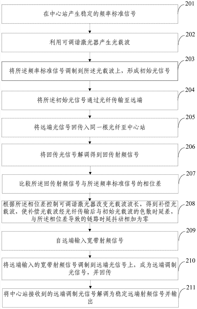
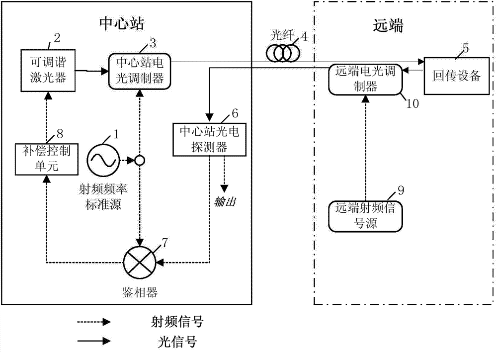
[0064] The embodiment of the present invention first proposes a wideband signal delay stable transmission method, see figure 2 ,include:
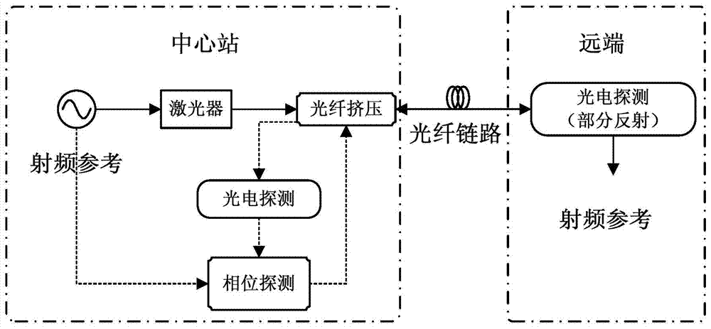
[0065] Step 201: Generate a stable frequency standard signal at the central station.
[0066] Step 202: Use a tunable laser to generate an optical carrier.
[0067] Step 203: modulate the frequency standard signal onto the optical carrier to form an initial optical signal.
[0068] Step 204: Transmit the initial optical signal to the remote end through an optical fiber.
[0069] Step 205: Pass the remote optical signal back into the same optical fiber to the central station.
[0070] Step 206: Demodulate the return optical signal to obtain the return radio frequency signal.
[0071] Step 207: Compare the phase difference between the returned radio frequency signal and the frequency standard signal.
[0072] Step 208: Control the tunable laser to change the wavelength of the optical carrier according to the phase difference to obtain the compensated optical carrier, so that the compensation optical carrier has a dispersion delay difference from the initial optical carrier after being transmitted through the optical fiber, and the link time caused by the phase difference The delay jitter adds to zero.
[0073] Step 209: Input a broadband radio frequency signal from the remote end.
[0074] Step 210: Modulate the wideband radio frequency signal input from the far end to the far end optical signal to become the far end modulated optical signal and transmit it back.
[0075] Step 211: Demodulate the remote modulated optical signal received by the central station into a stable remote radio frequency signal and output it.
[0076] It can be seen that in the broadband signal delay stable transmission method proposed in the embodiment of the present invention, the delay jitter of the optical fiber link is obtained by comparing the phase difference between the return radio frequency signal transmitted back and forth and the radio frequency standard signal. Tuning the laser changes the laser wavelength, and compensates for this jitter by generating different dispersion delays when different wavelengths are transmitted in the fiber, and finally realizes the stable return of the remote broadband radio frequency signal frequency and phase to the central station for output. The invention utilizes the optical fiber as the transmission medium and the compensation device at the same time, does not need to add an additional compensation device to realize the phase/frequency jitter compensation process, the system structure is simple and the practicability is strong.
[0077] In addition, the present invention obtains different dispersion delays to compensate for the jitter of the fiber link by changing the laser wavelength, the compensation range is larger, and since the dispersion delay is proportional to the length of the fiber, the longer the fiber, the larger the compensation range; At the same time, the present invention can ensure that the total time delay of the optical fiber link remains constant, can modulate and transmit radio frequency standard signals of different frequencies on the link, the bandwidth of the transmission link is large, and it is suitable for the transmission of time signals.
[0078] In an embodiment of the present invention, the RF frequency standard source is made to generate a stable single frequency point frequency standard signal, the center frequency of which is ω, and the initial phase is The single frequency point frequency standard signal is modulated onto the optical carrier, and the carrier wavelength λ is transmitted to the remote end through the optical fiber. A part of the optical signal at the remote end is reflected into the same optical fiber and transmitted back to the central station.
[0079] Suppose the time delay jitter introduced by the fiber link due to temperature changes and vibration is Δτ path; The optical signal returned to the central station is demodulated by the photodetector and restored to a radio frequency signal. Its phase is It can be expressed as:
[0080] The recovered RF signal after the round-trip transmission compares the phase difference with the source signal through a phase detector to obtain the error phase: According to this error signal 2ωΔτ path , Control the tunable laser and change the wavelength of the laser to λ+Δλ. At this time, the radio frequency signal modulated on the optical carrier is compared with the radio frequency signal modulated on the optical carrier λ. After transmission through the optical fiber, there will be a chromatic dispersion. Delay: Δτ disp =D·L·Δλ, where D is the dispersion coefficient of the single-mode fiber, and L is the length of the fiber.
[0081] After the optical signal is transmitted to the remote end, it is restored to a radio frequency signal by the photodetector, and it has experienced path And Δτ disp Two kinds of delay changes, the phase can be expressed as:
[0082]
[0083] Pass the error signal 2ωΔτ at the central station path Change the laser wavelength to meet After the compensation loop is locked through the compensation algorithm, 2ωΔτ path +2ωΔτ disp =0, so The phase of the remote frequency standard signal is consistent with the phase of the frequency standard source signal, that is, the transmission phase of the transmission system is stable, so the frequency of the remote signal can also remain stable.
[0084] In another embodiment of the present invention, in order to amplify the signal in the optical fiber link, preferably, after the remote optical signal is transmitted back to the same optical fiber to the central station, the returned optical signal is demodulated to obtain the return optical signal. Before transmitting the radio frequency signal, it may also include: signal amplification of the return optical signal. After the return, and before demodulating the remote modulated optical signal received by the central station into a stable remote radio frequency signal and outputting it, it may further include: signal amplifying the received remote modulated optical signal.
[0085] In an embodiment of the present invention, in order to obtain a higher quality radio frequency signal, preferably, after demodulating the return optical signal to obtain the return radio frequency signal, compare the return radio frequency signal with the frequency standard signal. Before the phase difference, it may also include: performing radio frequency amplification and filtering on the returned radio frequency signal. After demodulating the remote modulated optical signal received by the central station into a stable remote radio frequency signal, before outputting, it may further include: performing radio frequency amplification and filtering on the stable remote radio frequency signal.
[0086] The embodiment of the present invention also provides a broadband signal delay stable transmission system, such as image 3 Shown, including:
[0087] Radio frequency standard source 1, respectively connected to the central station electro-optical modulator and phase detector, used to generate stable frequency standard signals at the central station;
[0088] The tunable laser 2 is respectively connected with the central station electro-optical modulator and the compensation control unit to generate the optical carrier;
[0089] The central station electro-optical modulator 3 is also connected to an optical fiber, and is used to modulate the frequency standard signal onto the optical carrier to form an initial optical signal;
[0090] The optical fiber 4 is also connected to the return device, the remote electro-optical modulator and the central station photodetector respectively, and is used to transmit the initial optical signal to the remote end;
[0091] Return device 5, used to transmit the remote optical signal back into the same optical fiber to the central station; return the remote modulated optical signal;
[0092] The photodetector 6 of the central station is also connected with a phase detector to demodulate the return optical signal to obtain the return radio frequency signal; demodulate the remote modulated optical signal received by the central station into a stable remote radio frequency signal and output ;
[0093] The phase detector 7 is used to compare the phase difference between the return radio frequency signal and the frequency standard signal;
[0094] The compensation control unit 8 is connected to the phase detector and the tunable laser, and is used to control the tunable laser to change the wavelength of the optical carrier according to the phase difference to obtain the compensated optical carrier, so that the compensated optical carrier has a dispersion with the original optical carrier after being transmitted through the optical fiber The delay difference is zero when added to the link delay jitter caused by the phase difference;
[0095] Remote radio frequency signal source 9 for inputting broadband radio frequency signals from the remote end;
[0096] The remote electro-optical modulator 10 modulates the broadband radio frequency signal input from the remote end to the remote optical signal to become a remote modulated optical signal.
[0097] In an embodiment of the present invention, such as Figure 4 As shown, in order to make the dispersion time delay difference between the compensated optical signal and the initial optical carrier after being transmitted through the optical fiber, add to the phase difference to zero, preferably, the compensation control unit 8 may include:
[0098] The phase difference calculation subunit 11 is used to calculate the phase difference between the return radio frequency signal and the frequency standard signal:
[0099] Let the center frequency of the frequency standard signal be ω, and the initial phase is The initial optical carrier wavelength is λ, and the time delay disturbance introduced by the fiber link due to temperature changes and vibration is Δτ path , The phase of the returned RF signal is Then the formula used to calculate the phase difference is
[0100] The wavelength changing subunit 12 is used to control the tunable laser to change the laser wavelength to λ+Δλ to satisfy Among them, D is the dispersion coefficient of the single-mode fiber, and L is the length of the fiber.
[0101] In another embodiment of the present invention, preferably, the return device 5 may be a Faraday rotating mirror, and/or a remote optical circulator.
[0102] In an embodiment of the present invention, preferably, it may further include: a central station optical circulator 13, respectively connected to the central station electro-optic modulator, optical fiber, and central station photodetector clockwise for controlling the optical signal of the central station Sequence transmission.
[0103] In another embodiment of the present invention, in order to amplify the return optical signal and the remote modulated optical signal, preferably, it may further include: a central station erbium-doped fiber amplifier 14 connected between the optical fiber and the central station photodetector It is used to amplify the return optical signal and the remote modulated optical signal.
[0104] In an embodiment of the present invention, in order to obtain a better radio frequency signal, preferably, it may further include: a return radio frequency amplifier 15 connected to the central station photodetector for radio frequency amplification of the return radio frequency signal ; Return filter 16, connected between the return radio frequency amplifier and the phase detector, used to filter the radio frequency amplified return radio frequency signal. The output radio frequency amplifier 17, which is connected to the photodetector of the central station, is used for radio frequency amplification of the stable remote radio frequency signal; the output filter 18, which is connected between the output radio frequency amplifier and the output terminal, is used for the radio frequency amplification Stabilize the remote RF signal for filtering.
[0105] The following takes the use of dispersion and time delay compensation to return radio frequency signals of 1205 MHz and 2460 MHz as an example to specifically describe the implementation process of an embodiment of the present invention. Such as Figure 5 , Image 6 Shown:
[0106] Step 501: Generate a stable frequency standard signal at the central station.
[0107] In this step, a 2420MHz RF frequency standard source is generated at the central station as a stable single frequency point frequency standard signal.
[0108] Step 502: Use a tunable laser to generate an optical carrier.
[0109] Step 503: Modulate the frequency standard signal onto the optical carrier to form an initial optical signal.
[0110] In this step, an electro-optical modulator is used to modulate the frequency standard signal onto the laser to form an initial optical carrier.
[0111] Step 504: Transmit the initial optical signal to the remote end through the optical fiber.
[0112] In the embodiment of the present invention, an optical fiber with a length of 10 km is used to transmit the initial optical signal to the remote end through the optical circulator.
[0113] Step 505: Pass the remote optical signal back into the same optical fiber to the central station.
[0114] In this step, a Faraday rotating mirror is used to transmit the remote optical signal back to the central station via the remote optical circulator.
[0115] Step 506: Amplify the return optical signal signal.
[0116] In this step, the central station erbium-doped fiber amplifier is used to amplify the returned optical signal.
[0117] Step 507: Demodulate the amplified return optical signal to obtain a return radio frequency signal.
[0118] In this step, the central station photodetector is used to demodulate the return optical signal to obtain the return radio frequency signal.
[0119] Step 508: Filter the returned radio frequency signal.
[0120] Step 509: Compare the phase difference between the returned radio frequency signal and the frequency standard signal.
[0121] In this step, let the center frequency of the frequency standard signal be ω, and the initial phase is The initial optical carrier wavelength is λ, and the time delay jitter introduced by the fiber link due to temperature changes and vibration is Δτ path , The phase of the returned RF signal is Then the formula used to calculate the phase difference is
[0122] Step 510: Control the tunable laser according to the phase difference to change the wavelength of the optical carrier to obtain the compensated optical carrier.
[0123] In this step, the tunable laser needs to be controlled to change the wavelength of the optical carrier to λ+Δλ to satisfy Among them, D is the dispersion coefficient of the single-mode fiber, and L is the length of the fiber.
[0124] Step 511: Input a broadband radio frequency signal from the remote end.
[0125] In this step, the wideband RF signal input from the far end is better to be different from the RF frequency standard source of the central station in order to better distinguish the two sets of signals on the optical carrier. In the embodiment of the present invention, remote radio frequency signals of 1205 MHz and 2460 MHz are respectively input from the remote end.
[0126] Step 512: Modulate the wideband radio frequency signal input from the remote end to the remote optical signal to become the remote modulated optical signal and transmit it back.
[0127] Step 513: Amplify the remote modulated optical signal.
[0128] Step 514: Demodulate the amplified remote modulated optical signal into a stable remote radio frequency signal.
[0129] Step 515: Filter the demodulated stable remote radio frequency signal and output it.
[0130] So far, the entire process of performing dispersion and delay compensation for the optical fiber link in the embodiment of the present invention, inputting from the remote end, and receiving the stable return remote radio frequency signal from the central station is completed.
[0131] It should be noted that the above is based on Figure 5 All the process descriptions are a preferred implementation process of the wideband signal delay and stable transmission method of the present invention. In the actual implementation of the frequency stabilization transmission method of the present invention, it can be figure 2 Arbitrary deformation based on the shown process, can be selected Figure 5 It can be realized by any step in the above, and the sequence of each step can also be adjusted as needed.
[0132] In the embodiment of the present invention, the phase noise suppression factor of both signals before and after compensation can reach 30, and as the test time increases, the suppression effect will be further improved. It can be seen that the embodiment of the present invention has an obvious inhibitory effect on the phase delay of the optical fiber link.
[0133] It can be seen that the embodiments of the present invention have the following beneficial effects:
[0134] In the broadband signal delay stable transmission method and system proposed in the embodiment of the present invention, the delay jitter of the optical fiber link is obtained by comparing the phase difference between the return radio frequency signal and the radio frequency standard signal transmitted back and forth, and then the delay jitter of the optical fiber link is obtained. Tuning the laser changes the laser wavelength, and compensates for this jitter by generating different dispersion delays when different wavelengths are transmitted in the optical fiber, and finally realizes the remote-end stable frequency and phase RF signal output. In the embodiment of the present invention, the optical fiber is used as the transmission medium and the compensation device at the same time, no additional compensation device is needed to realize the phase jitter compensation process, the system structure is simple, and the practicability is strong.
[0135] In addition, the embodiment of the present invention obtains different dispersion delays by changing the laser wavelength to compensate for fiber link jitter. The compensation range is larger, and since the dispersion delay is proportional to the length of the fiber, the longer the fiber, the greater the compensation range. At the same time, the embodiment of the present invention can ensure that the total time delay of the optical fiber link remains constant, and can adjust and transmit radio frequency standard signals of different frequencies on the link. The bandwidth of the transmitted link is large, and it is suitable for time signals. Transmission.
[0136] Finally, it should be noted that the above embodiments are only used to illustrate the technical solutions of the present invention, not to limit it; although the present invention has been described in detail with reference to the foregoing embodiments, those of ordinary skill in the art should understand that: The technical solutions recorded in the foregoing embodiments are modified, or some of the technical features are equivalently replaced; these modifications or replacements do not cause the essence of the corresponding technical solutions to deviate from the spirit and scope of the technical solutions of the embodiments of the present invention.

PUM

no PUM

Description & Claims & Application Information

We can also present the details of the Description, Claims and Application information to help users get a comprehensive understanding of the technical details of the patent, such as background art, summary of invention, brief description of drawings, description of embodiments, and other original content. On the other hand, users can also determine the specific scope of protection of the technology through the list of claims; as well as understand the changes in the life cycle of the technology with the presentation of the patent timeline. Login to view more.

Similar technology patents

Classification and recommendation of technical efficacy words

  • Simple system structure
  • Practical

Laser radar system

ActiveCN106707291ASimple system structureReduce Speckle NoiseElectromagnetic wave reradiationSpeed measurementLinear modulation
Owner:UNIV OF SCI & TECH OF CHINA
Why Eureka
Try Eureka