Transformer substation equipment video monitoring method based on RFID (Radio Frequency Identification) technique

A technology for video surveillance and substations, applied in the field of transformer equipment monitoring, can solve the problems of different functional locations, difficult to distinguish with human eyes, correlated real-time display, etc., to reduce misjudgment and misoperation, and improve the accuracy.

Active Publication Date: 2014-04-02
STATE GRID CORP OF CHINA +2
View PDF9 Cites 22 Cited by
  • Summary
  • Abstract
  • Description
  • Claims
  • Application Information

AI Technical Summary

Problems solved by technology

[0002] In recent years, with the rapid development of the smart grid, the research on the substation visual monitoring system has achieved great results, which can realize the image analysis of the main equipment, but the remote sequence control and video intelligent inspection of the substation still need the operator to manually judge according to the image information Device number, electric power When the primary device is observed through the camera at close range, it is difficult to distinguish between two devices of the same manufacturer and the same model, whether it is human eyes or image recognition. The biggest difference between them is that their functional positions are completely different.
Moreover, the static and dynamic parameters of these equipment (such as equipment status monitoring parameters, equipment operation year, maintenance times, etc.) cannot be associated with real-time display in the same interface, which affects the decision-making of operators to a certain extent

Method used


Image

  • Transformer substation equipment video monitoring method based on RFID (Radio Frequency Identification) technique

Examples


Embodiment Construction

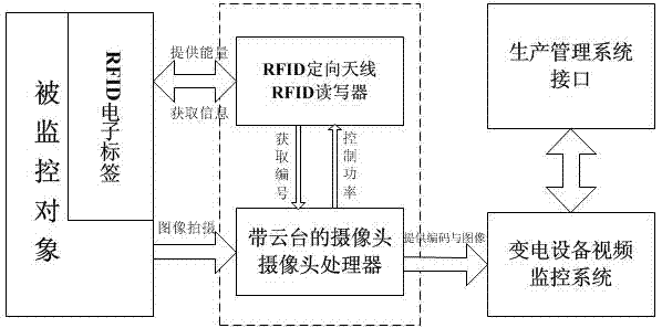
[0021] Refer to attached figure 1 : Taking the steps described in the summary of the invention as the main line, combined with the attached figure 1 The working principle and data flow process of the present invention in the specific implementation process are described.

[0022] Before the substation equipment is completed and put into production, the equipment's material classification, supplier, order number, equipment classification, equipment number, original manufacturer, and the equipment's unique functional position (ISPG) code in the entire system are written into the RFID through the handheld device In the user area of ​​the electronic label. The functional location code of the equipment not only indicates the spatial location of the equipment, but also indicates the functional location of the equipment in the entire power grid, which indicates the role of the equipment in the power grid. Use this code to retrieve the health history information of materials, equipm...


PUM


Abstract

The invention relates to a transformer equipment monitoring technique, in particular to a transformer substation equipment video monitoring method based on an RFID (Radio Frequency Identification) technique. The method comprises the steps that a functional position code, namely an ISPG (Identification System of Power Grid) code of electrical equipment is written into an RFID ultra-high-frequency electronic tag with high impedance and high electromagnetic interference; directional antennas are mounted on camera cradle heads; the antennas are rotated along with the cradle heads; electronic tag content of a shot object is read; and the electronic tag content is transmitted to a background monitoring system. Transformer substation centralized control personnel feed back an equipment picture and the equipment number to a monitoring interface by the method, so that a user can judge a health status of the equipment, a patrol record is filled in, and the accuracy of defect finding is improved. The method has the technical effects that auxiliary identification is synchronously performed on the equipment while the electrical equipment is shot by cameras; the RFID directional technique and a camera cradle head control technique are organically combined innovatively; a visual informatization-associated integrated interface is provided quickly, effectively and accurately; and misjudgment and misoperation of defects and accidents can be reduced.

Description

technical field [0001] The invention relates to a transformer equipment monitoring technology, in particular to a video monitoring method for substation equipment based on RFID technology. Background technique [0002] In recent years, with the rapid development of the smart grid, the research on the substation visual monitoring system has achieved great results, which can realize the image analysis of the main equipment, but the remote sequence control and video intelligent inspection of the substation still need the operator to manually distinguish according to the image information Device number, electric power When the primary device is observed through the camera at close range, it is difficult to distinguish two devices of the same manufacturer and model by human eyes or image recognition. The biggest difference between them is that their functional locations are completely different. Moreover, the static and dynamic parameters of these equipment (such as equipment sta...

Claims


Application Information

Patent Timeline
Patent Type & Authority Applications(China)
IPC IPC(8): H04N7/18G06K7/10H04N5/232H02J13/00
Inventor 黄春红蔡鸿扬杨世仁林少山李鹏陈明詹银
Owner STATE GRID CORP OF CHINA
Why Eureka
Try Eureka