Intraocular foreign body forceps

An intraocular foreign body and tweezers technology, applied in the field of intraocular foreign body tweezers, can solve the problems of increasing the risk of endophthalmitis, increasing the retina, and long operation time, reducing the risk and complications of surgery, overcoming the instability of foreign bodies, and improving The effect of surgical success

Active Publication Date: 2014-04-09
苏州碧利医疗科技有限公司
View PDF8 Cites 6 Cited by
  • Summary
  • Abstract
  • Description
  • Claims
  • Application Information

AI Technical Summary

Problems solved by technology

[0005] At present, the intraocular foreign body tweezers have the following disadvantages: when using the surgical tweezers with the above structure to grab foreign bodies, the diameter of the sclera puncture port for conventional 20G vitrectomy is 1mm, and the existing foreign body tweezers are suitable for irregular intraocular foreign bodies, such as ferromagnetic It is difficult to successfully grasp debris-like foreign bodies at one time, so repeated clamping is required, which may increase the risk of retinal hemorrhage and tears; and the operation time is longer, and the risk of endophthalmitis is greatly increased; in addition, long-term operation is harmful to patients and surgeons. physical strength is also a test
At the same time, during the foreign body removal process of the existing foreign body tweezers, on the one hand, due to the uneven force on each part of the irregular foreign body, touching the ball wall when leaving the regular scleral incision is very easy to cause the foreign body to fall off again, and the foreign body will cause secondary damage to the retina. On the other hand, even if the foreign body does not fall off, the foreign body will cause scleral damage when it passes through the scleral opening, which may affect the scleral seal, cause scleral leakage and increase the risk of endophthalmitis

Method used


Image

  • Intraocular foreign body forceps
  • Intraocular foreign body forceps
  • Intraocular foreign body forceps

Examples


Embodiment Construction

[0022] The present invention will be described in further detail below in conjunction with the accompanying drawings and specific embodiments. It should be understood that the specific embodiments described here are only used to explain the present invention, not to limit the present invention.

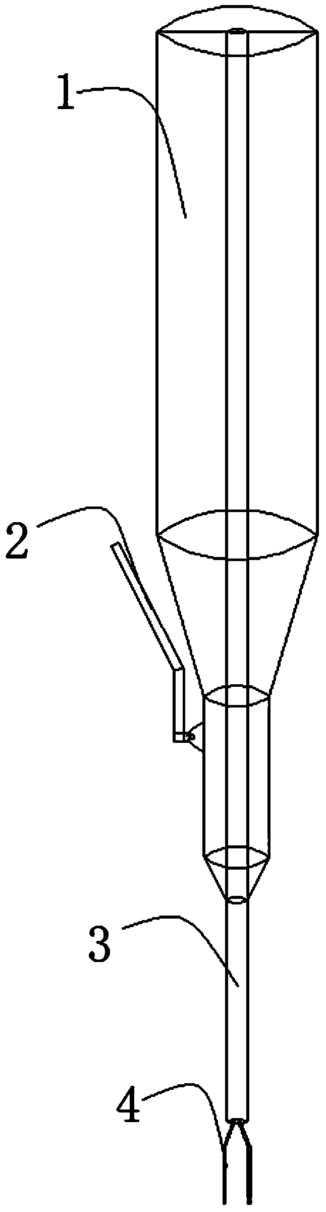
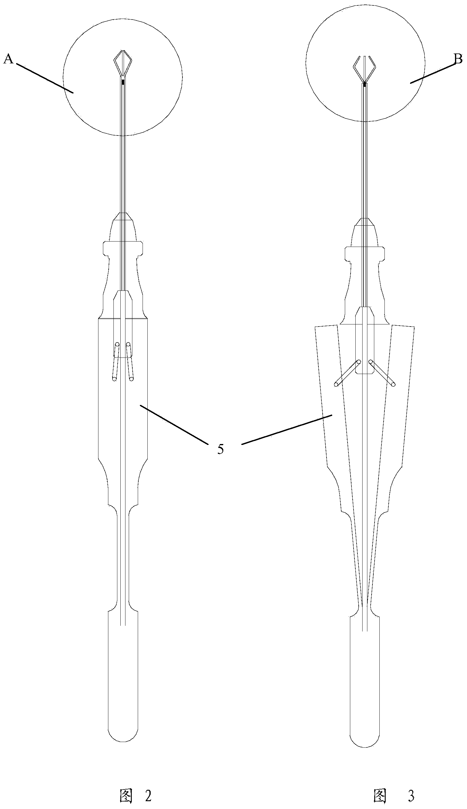
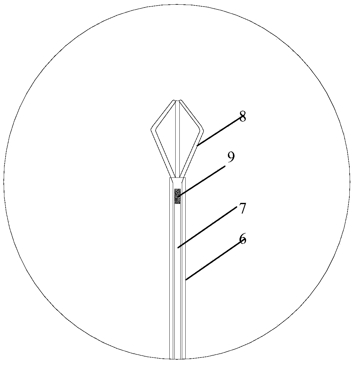
[0023] Such as Figure 2-5 As shown, the intraocular foreign body tweezers of the present invention include a handle 5, a tweezer claw portion and an outer sleeve 6, and the tweezer claw portion includes a fixed tube 7 fixedly connected to the handle and a non-magnetic tweezer claw 8 positioned at the front end of the fixed tube. The outer sleeve 6 is set on the outside of the fixed tube and can be driven to slide back and forth to control the tweezers to draw close together or open away from each other. A magnetic component 9 is fixedly arranged at the front end of the fixed tube, preferably the magnetic The component is a magnetic column or a magnetic block. When the outer sleeve d...


PUM


Abstract

The invention discloses intraocular foreign body forceps, comprising hand shanks, forceps claw sections and an outer sleeve, wherein each forceps claw section comprises a fixed tube and a non-magnetic forceps claw; each fixed tube is fixedly connected with each hand shank; each non-magnetic forceps claw is fixed at the front end of each fixed tube; the outer sleeve is sleeved on the outer sides of the fixed tubes and can be driven to slide back and forth, so as to control the forceps claws to get close to be folded or depart to expand; a magnetic component is fixedly arranged at the front end of each fixed tube, and is contained into the outer sleeve when the forceps claws get close to each other; at least the end part of the magnetic component is exposed out of the port of the outer sleeve when the outer sleeve slides backwards to control the forceps claws to expand. By adopting the intraocular foreign body forceps, the difficulty in the process of taking out an irregular magnetic foreign body inside the ball is solved, the defects that the foreign body is unstable and easy to fall off are overcome, the stability in the process of taking out the foreign body is increased, the achievement ratio of operation is improved, the operation time is reduced, the surgical risk and complication are reduced, and the intraocular foreign body forceps are safe to operate.

Description

technical field [0001] The invention relates to the technical field of ophthalmic tools, in particular to forceps for intraocular foreign bodies. Background technique [0002] Eye trauma, especially eye trauma with intraocular foreign bodies, is one of the important blinding factors in ophthalmology. If it is not handled properly, it will lead to serious consequences such as blindness and eyeball atrophy. With the development of vitrectomy microsurgery, the removal of foreign bodies under a microscope has significantly improved the success rate of removal of intraocular foreign bodies. [0003] Conventional foreign body tweezers consist of a handle and a head, with a total length of about 150mm. The handle has a thumb pressing area or other action structures to control the opening and clamping of the head end of the tweezers; the orientation of the head end can be rotated and adjusted to make it easier to hold foreign bodies in the eye. According to the number of tweezers,...

Claims


Application Information

Patent Timeline
Patent Type & Authority Applications(China)
IPC IPC(8): A61F9/007
Inventor 颜华
Owner 苏州碧利医疗科技有限公司
Why Eureka
Try Eureka