Hydraulic cylinder with throttling buffer mechanism

The technology of a buffer mechanism and a hydraulic cylinder, which is applied in the field of hydraulic cylinders, can solve the problems of complex structure and high assembly precision of the buffer hydraulic cylinder, and achieve the effects of simple structure, improved efficiency and good buffering effect.

Inactive Publication Date: 2014-04-09
ANHUI KAIXIN ELECTROMECHANICAL SCI & TECH
View PDF6 Cites 0 Cited by
  • Summary
  • Abstract
  • Description
  • Claims
  • Application Information

AI Technical Summary

Problems solved by technology

[0003] The purpose of the present invention is to solve the problems of the existing buffer hydraulic cylinder with complex structure and high assembly precision, and to provide a hydraulic cylinder with throttling buffer mechanism

Method used


Image

  • Hydraulic cylinder with throttling buffer mechanism
  • Hydraulic cylinder with throttling buffer mechanism

Examples


Embodiment 1

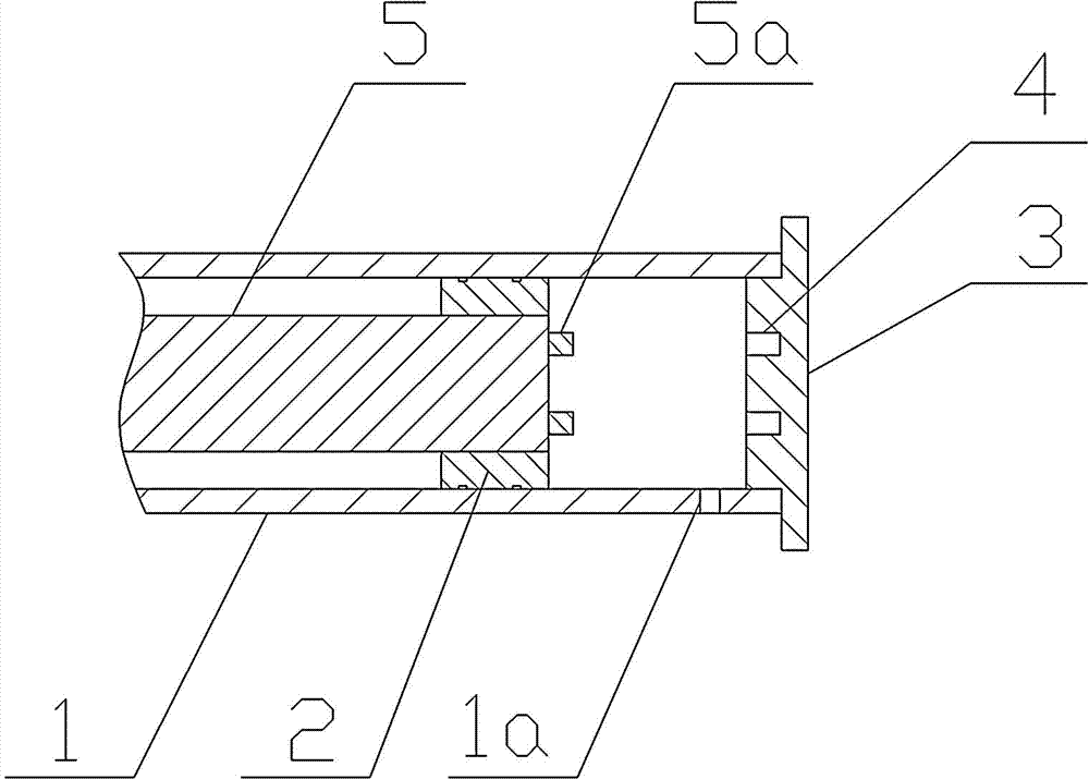
[0016] Such as figure 1 As shown, a hydraulic cylinder with a throttling buffer mechanism provided by the present invention includes a cylinder body 1, an oil injection hole 1a is arranged on one side of the cylinder body, a piston rod 5 is arranged in the inner cavity of the cylinder body, and a piston rod is provided on the piston rod The piston 2 slidingly fitted with the inner cavity of the cylinder is provided with end caps 3 at both ends of the cylinder, wherein a group of buffer holes 4 are arranged on the cylinder head at one end of the cylinder, and the axial direction of each buffer hole is aligned with the axis of the end cap. Oriented parallel to each other, one end of the piston rod 5 is provided with a set of buffer columns 5a, and each buffer column 5a is slidably fitted with the corresponding buffer hole 4 respectively.

Embodiment 2

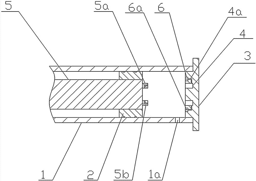
[0018] Such as figure 2 As shown, a hydraulic cylinder with a throttling buffer mechanism provided by the present invention includes a cylinder body 1, an oil injection hole 1a is arranged on one side of the cylinder body, a piston rod 5 is arranged in the inner cavity of the cylinder body, and a piston rod is provided on the piston rod The piston 2 slidingly fitted with the inner cavity of the cylinder is provided with end caps 3 at both ends of the cylinder, wherein a group of buffer holes 4 are arranged on the cylinder head at one end of the cylinder, and the axial direction of each buffer hole is aligned with the axis of the end cap. parallel to each other, a set of throttle nozzles 6 is provided on the cylinder head at one end of the cylinder, each throttle nozzle is provided with a throttle hole 6a, and one end of the throttle hole 6a communicates with the corresponding buffer hole 4 through the return hole 4a One end of the piston rod 5 is provided with a group of buff...


PUM


Abstract

The invention relates to a hydraulic cylinder with a throttling buffer mechanism. The hydraulic cylinder comprises a cylinder body (1). One side of the cylinder body is provided with an oil filler (1a). A piston rod (5) is arranged in an inner cavity of the cylinder body. The piston rod is provided with a piston (2) in sliding fit with the inner cavity of the cylinder body. Two ends of the cylinder body are provided with end covers (3). The hydraulic cylinder is characterized in that the end cover at one end of the cylinder body is provided with a buffer hole group (4), and the axis of each buffer hole is parallel to the axis of the end cover; one end of the piston rod is provided with a buffer post group (5a), and the buffer posts (5a) are in sliding fit with the corresponding buffer holes (4). The hydraulic cylinder has the advantages that the structure is simple, buffer effect is good, assemblers can assemble more efficiently, and manufacture cost is low.

Description

technical field [0001] The invention relates to a hydraulic cylinder, in particular to a hydraulic cylinder with buffer function. Background technique [0002] In the hydraulic system, the hydraulic cylinder is often used to drive the mechanism with a certain quality. When the hydraulic cylinder moves to the end of the stroke, it has a large kinetic energy. If the deceleration is not performed, the hydraulic cylinder piston and the cylinder head will have a mechanical collision, resulting in impact and noise. destructive. In order to alleviate and prevent this hazard from happening, it is necessary to set up a buffer device in the cylinder body. However, the existing hydraulic cylinders with buffer devices not only have complex structures and high manufacturing costs, but also require high assembly accuracy. Contents of the invention [0003] The object of the present invention is to solve the problems of the existing buffer hydraulic cylinder with complex structure and ...

Claims


Application Information

Patent Timeline
Patent Type & Authority Applications(China)
IPC IPC(8): F15B15/22
Inventor 史宝林
Owner ANHUI KAIXIN ELECTROMECHANICAL SCI & TECH
Why Eureka
Try Eureka