Gas exhaust device for aerostat

An exhaust device and aerostat technology, applied in the field of aerostats, can solve the problems of long closing time of the valve cover 200, affecting the accuracy of pressure difference control, affecting the precise control of airbag pressure difference, etc., so as to achieve short closing time and reduce The effect of collision and smooth discharge

Inactive Publication Date: 2014-04-09
ACAD OF OPTO ELECTRONICS CHINESE ACAD OF SCI
View PDF6 Cites 16 Cited by
  • Summary
  • Abstract
  • Description
  • Claims
  • Application Information

AI Technical Summary

Problems solved by technology

[0006] 2. The valve cover 200 takes a long time to close, which affects the precise control of the pressure difference inside and outside the airbag
In addition, the pitch of the screw mandrel 400 also requires that it cannot be too large, and the motor 300 cannot rotate too fast or the torque is not enough, and at the same time, in order to facilitate exhaust, the opening stroke of the valve cover 200 needs to be very long. When the valve cover is 200, the movement of the screw rod 400 nut (thread) cannot be too fast, generally it takes 5-10 seconds. During this process, the pressure difference inside and outside the airbag has changed. When the command to close the exhaust device is started, it takes 5-10 seconds for the valve to be completely closed, so that when it is closed, the pressure difference has become about 3.8g, so the valve is not closed in time, which will affect the pressure difference control accuracy

Method used


Image

  • Gas exhaust device for aerostat
  • Gas exhaust device for aerostat
  • Gas exhaust device for aerostat

Examples


Embodiment Construction

[0035] In order to make the purpose, technical solution and advantages of the present invention more clear, the following will describe the specific implementation manners of the present invention in detail according to specific examples and with reference to the accompanying drawings. However, it should be noted that the examples described herein are only used to explain the present invention, rather than to limit the protection scope of the present invention.

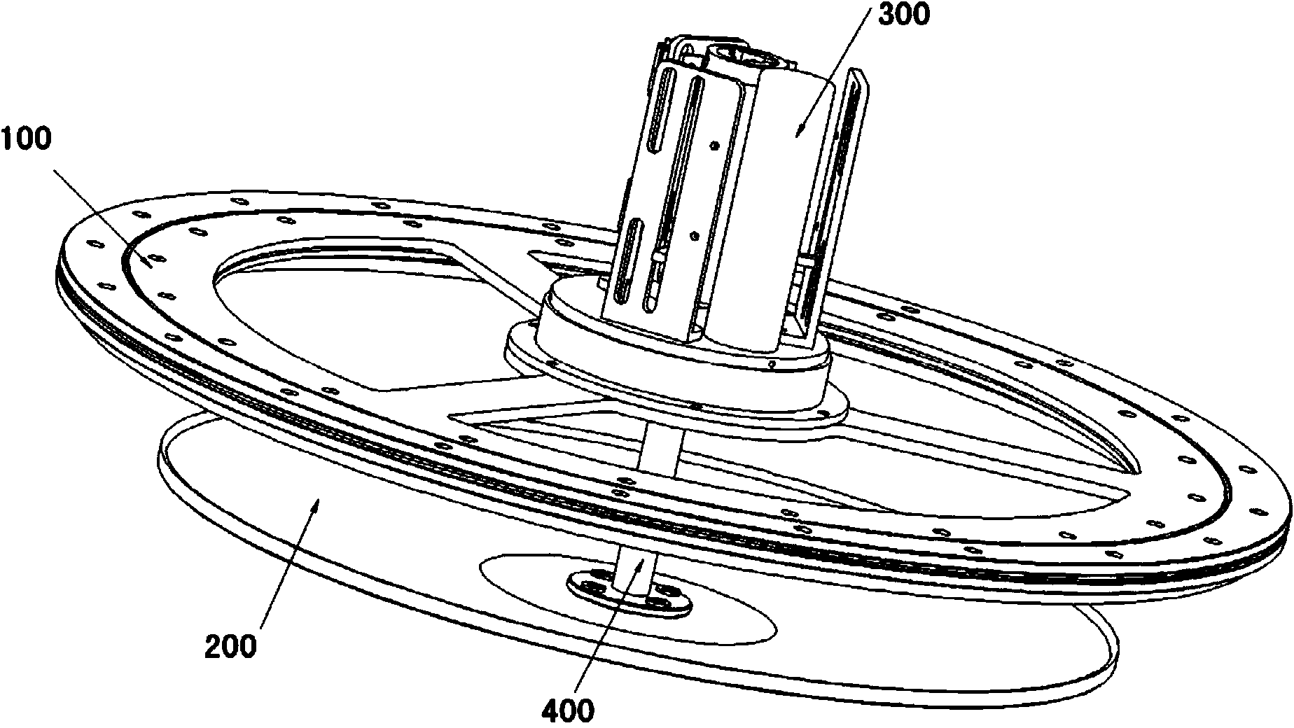
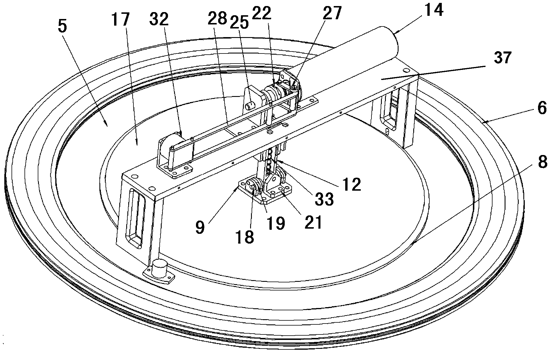
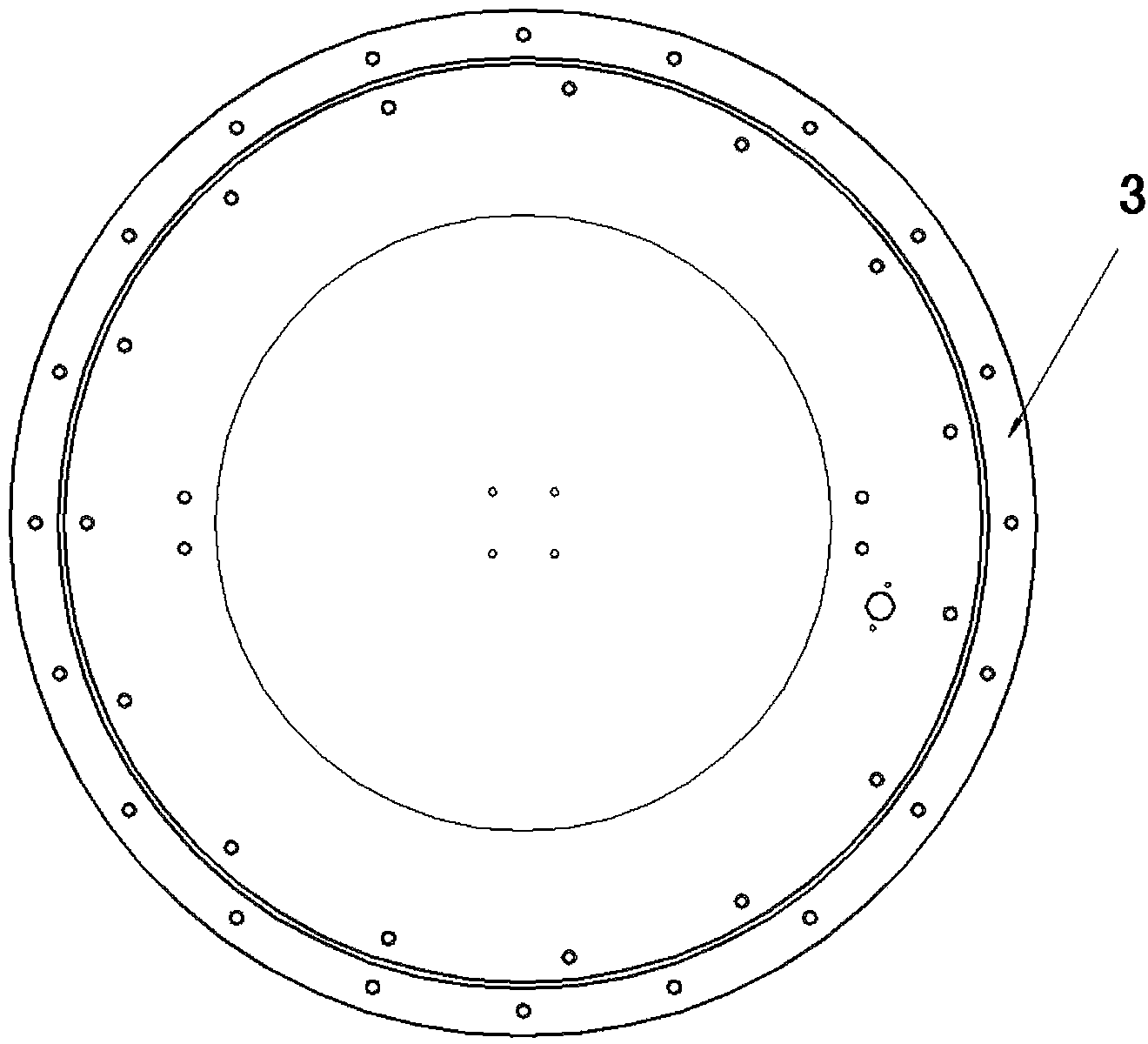
[0036] Such as figure 2 As shown, the exhaust device for an aerostat according to the present invention includes a valve including a valve body 5 and a valve cover 17 . Wherein the valve body 5 has a valve port 51, preferably the valve port 51 is a central through hole, so that the valve body has a ring shape as a whole. The valve body 5 is fixed on the suction and exhaust port of the air bag along the circumferential direction of the aerostat air bag through the valve body installation mechanism. The valve cover 1...


PUM


Abstract

The invention provides a gas exhaust device for an aerostat. The gas exhaust device comprises a valve. The valve comprises a valve body and a valve cover, wherein the valve body is provided with a valve port, and the valve cover covers the valve port in an openable and closable mode. The valve body is fixed to a gas suction and exhaust port of a gas bag in the circumferential direction of the gas bag of the aerostat through a valve body installing mechanism, wherein the valve cover covers the valve port in the openable and closable mode through a control device with an opening and closing device. The opening and closing device comprises a drive mechanism and a valve cover reset mechanism, wherein the drive mechanism is connected with the valve cover and used for driving the valve cover to be vertically lifted at a preset height and driving the valve cover to tilt and be kept at a certain angle after the valve cover is vertically lifted at the preset height. The valve cover reset mechanism is connected with the valve cover and pushes the valve cover to reset to cover the valve port after the drive mechanism stops driving the valve cover. The valve cover can be vertically lifted and can tilt at the same time, the gas exhaust area is increased, collision between gas and the valve cover is reduced, and the gas exhaust speed is increased.

Description

technical field [0001] The invention relates to the technical field of aerostats, in particular to an exhaust device for aerostats. Background technique [0002] An aerostat generally refers to a soft-structure aircraft whose specific gravity is lighter than air and relies on atmospheric buoyancy to lift into the air. The aerostat is composed of an airbag made of polymer composite material and various equipment and payloads arranged on the airbag. The airbag is filled with a buoyant gas with a density lower than that of air, and the density difference between the inside and outside of the airbag provides the aerostat buoyancy, thereby completing the lift-off of the aerostat. Aerostats generally include balloons and airships. The formed aerostat lifts off from the ground, and as the flight altitude increases, the density of the outside air and atmospheric pressure gradually decrease, and the volume of the buoyant gas in the aerostat expands rapidly. In order to be safe and...

Claims


Application Information

Patent Timeline
IPC IPC(8): F16K31/06B64B1/62F16K1/18F16K1/32F16K1/36
CPCB64B1/62F16K1/18F16K1/32F16K1/36F16K31/047F16K31/0658
Inventor 王立祥何小辉祝榕辰张冬辉
Owner ACAD OF OPTO ELECTRONICS CHINESE ACAD OF SCI
Why Eureka
Try Eureka