
The sealing device of the lower part of the trolley of the blast ring cooler

A technology of sealing device and annular cooler, which is applied in the direction of processing discharged materials, furnaces, lighting and heating equipment, etc., can solve the problems of periodic thermal deformation of annular cooler, reduced air leakage rate, high air leakage rate, etc., to improve waste heat recovery efficiency, saving power consumption, and reducing production costs

Inactive Publication Date: 2015-08-26
王为
View PDF8 Cites 0 Cited by
  • Summary
  • Abstract
  • Description
  • Claims
  • Application Information

AI Technical Summary

Problems solved by technology

When the ring cooler is running, due to various reasons, the sealing body is squeezed, torn, torn off, and worn. In particular, the sealing rubber of the first section of the ring cooler quickly ages and fails under the action of high temperature, resulting in the lower part of the ring cooler trolley The air leakage rate between the top of the bellows is as high as 20%-30%
[0006] ZL200710034675.8 invented a mechanical sealing device of the "Sealing Device for the Lower Part of the Trolley of the Ring Cooler", which overcomes the disadvantages of the traditional seal and solves the problem that the sealing skin is squeezed and torn when the radial movement of the ring cooler is running. , tearing off, and deformation and falling off of the conical sealing plate. The sealing effect is better than the traditional mechanical seal, and the air leakage rate is reduced.
However, problems such as periodic thermal deformation of the annular cooler, movement of the trolley, wear compensation of the sealing plate, and high-temperature aging failure of a section of sealing rubber have not been resolved.
The air leakage rate is still high after running for a period of time

Method used


Image

  • The sealing device of the lower part of the trolley of the blast ring cooler
  • The sealing device of the lower part of the trolley of the blast ring cooler
  • The sealing device of the lower part of the trolley of the blast ring cooler

Examples


Embodiment Construction

[0019] The specific implementation manner of the present invention will be further described below in conjunction with the accompanying drawings.

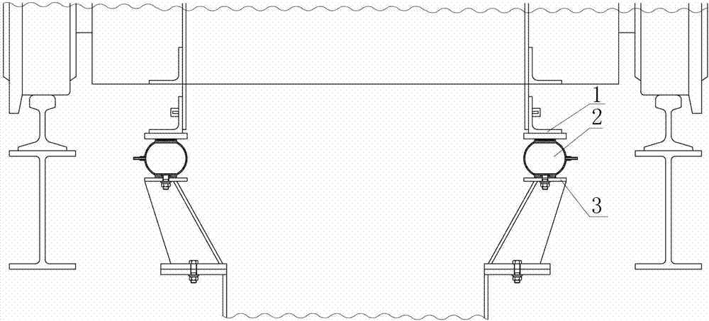
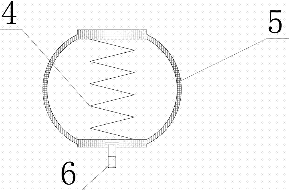
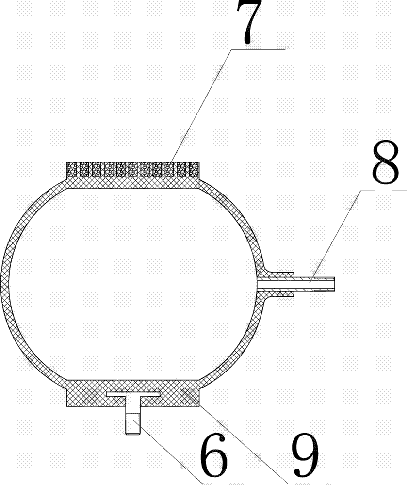
[0020] like figure 1 , 2 As shown in and 3, the lower sealing device of the trolley of the blast ring cooler of the present invention includes an upper movable sealing body 1 connected to the lower rail of the trolley, and a lower fixed sealing body 3 fixed on the grooved beam of the bellows. It is characterized in that an airtight bladder seal body 2 is provided between the upper movable seal body 1 and the lower fixed seal body 3, and the airtight bladder seal body 2 is slidably connected with the upper movable seal body 1, The airtight capsule sealing body 2 is fixedly connected with the lower fixed sealing body 3, and the structure of the airtight capsule sealing body 2 is a strip-shaped capsule structure with a closed cavity.

[0021] The airtight bag-type sealing body 2 is a metal braided airbag, and this metal braided airb...


PUM


Abstract

The invention belongs to the technical field of annular cooler equipment, and particularly relates to a sealing device for the lower part of a trolley of an air-blast annular cooler. The sealing device comprises upper part moving sealing bodies and lower part fixing sealing bodies, and is characterized in that sealed bag type sealing bodies are arranged between the upper part moving sealing bodies and the lower part fixing sealing bodies, and the sealed bag type sealing bodies are connected with the upper part moving sealing bodies in a sliding manner, and are connected with the lower part fixing sealing bodies fixedly. The sealing device can replace liquid sealing, and can overcome the deficiency of the mechanical sealing. A high-temperature-resistant metal woven bag achieves high-temperature seal at the section I of the annular cooler. Through a rubber cavity air bag, the sealing of other cooling sections, except for the section I of the annular cooler, can be realized, gaps between the upper part moving sealing bodies and the lower part fixing sealing bodies can be realized by automatically regulating the pressure of the rubber cavity air bag, the air leakage rate, about 5%-8%, at the lower part of the annular cooler can be reduced, and the recycling rate of the residual heat of the annular cooler can be greatly improved.

Description

technical field [0001] The invention belongs to the technical field of annular cooler equipment, and in particular relates to a sealing device for the lower part of a trolley of a blast annular cooler. Background technique [0002] The sintering ring cooler is a ring-shaped continuous rotary motion blast cooling equipment composed of a trolley, a rotary frame and a fixed bellows. The container consisting of the top of the ring cooler trolley and the upper fence of the trolley is filled with red hot sintered ore with a temperature of about 850°C. The air blown by the blower passes through the grate plate of the trolley through the bellows and exchanges heat with the hot sintered ore on the trolley to take away the heat, cooling the hot sintered ore to below 150°C. The trolley moves along the circular track driven by the slewing frame. The trolley and the upper and lower sills of the trolley are fixed on the slewing frame, which moves relative to the bellows fixed at the lowe...

Claims


Application Information

Patent Timeline
Patent Type & Authority Patents(China)
IPC IPC(8): F27D15/02
Inventor 王为
Owner 王为
Learn More