Acid seed reactor in cotton seed machining
A cotton seed and reactor technology, which is applied in the direction of seed and rhizome treatment, application, sequence/logic controller program control, etc., can solve the problem of too much acid, the incompatibility of seed feeding and acid supply mechanism, and the influence of The quality of seed processing and other issues, to achieve the effect of low seed damage, good uniformity of acid application, and reduce excessive dependence
- Summary
- Abstract
- Description
- Claims
- Application Information
AI Technical Summary
Problems solved by technology
Method used
Image
Examples
Embodiment 1
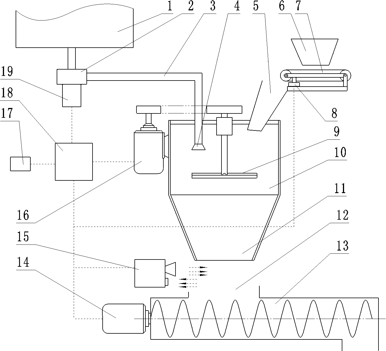
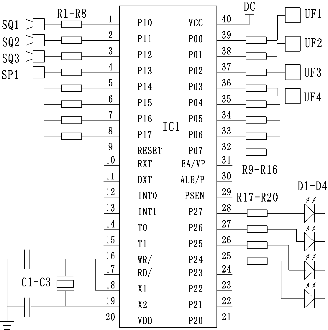
[0018] Embodiment 1: with reference to attached Figure 1~2 , is a structural schematic diagram of Embodiment 1 of the present invention, including a reaction chamber 10 formed of a cylindrical object provided with a feed inlet 5 and a discharge outlet 11, and the reaction chamber 10 is provided with a seed throwing mechanism and an acid supply mechanism, The acid supply mechanism includes an acid liquid tank 1, an acid supply pump 2, an acid supply pump motor 19, an acid supply pipe 3 and an acid supply nozzle 4. The seed throwing mechanism includes a throwing mechanism motor 16 transmission mechanism and a centrifugal spinner 9, and the discharge port After 11, there is a stirring mechanism, which includes a tank body 13, a stirring tank feed port 12, a stirring propulsion mechanism, and a stirring motor 14. The acid pump motor 19, the throwing mechanism motor 16, and the stirring motor 14 are all controlled by frequency converters. , the central controller 18 is an 8051 int...
Embodiment 2
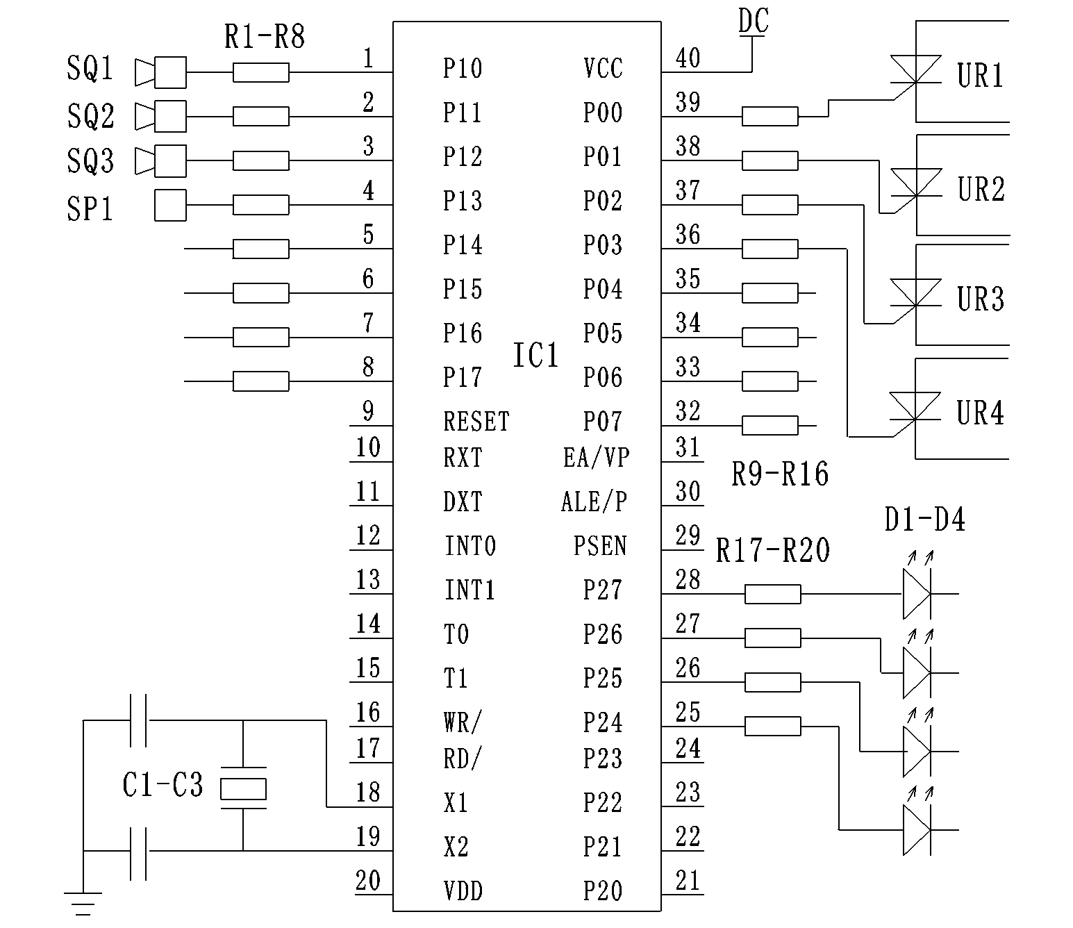
[0021] Embodiment 2: refer to image 3 , is a circuit diagram of Embodiment 2 of the present invention. Compared with Embodiment 1, the difference of this embodiment is that the frequency converters UF1-UF4 are replaced by switching thyristors UR1-UR4, and the signal output terminal of the central controller 18 is connected to control the control of thyristors UR1-UR4. Pole, and then respectively control the work of the acid supply pump motor 19, the throwing mechanism motor 16, the stirring motor 14 and the material conveying motor.
[0022] The aforementioned switching thyristors UR1-UR4 can also be replaced by bidirectional thyristors.
Embodiment 3
[0023] Embodiment 3: refer to Figure 4 , is a circuit diagram of Embodiment 3 of the present invention. With Embodiment 1, the difference of this embodiment is that the frequency converters UF1-UF4 are replaced by switching transistors BK1-BK4, and the signal output terminal of the central controller 18 is connected to and controls the control poles of the transistors BK1-BK4, And then respectively control the work of the acid supply pump motor 19, the throwing mechanism motor 16, the stirring motor 14 and the material conveying motor.
PUM
 Abstract
Description
Claims
Application Information
 - R&D
- Intellectual Property
- Life Sciences
- Materials
- Tech Scout
- Unparalleled Data Quality
- Higher Quality Content
- 60% Fewer Hallucinations
Browse by: Latest US Patents, China's latest patents, Technical Efficacy Thesaurus, Application Domain, Technology Topic, Popular Technical Reports.
© 2025 PatSnap. All rights reserved.Legal|Privacy policy|Modern Slavery Act Transparency Statement|Sitemap|About US| Contact US: help@patsnap.com


