
Mechanical joints and robotic arms using them

A technology of mechanical joints and robotic arms, applied in the direction of manipulators, program-controlled manipulators, manufacturing tools, etc., can solve the problems of difficult sharing of components, unreduced cost, and different sizes of robotic arms, so as to reduce the range of deceleration, save space configuration, The effect of increasing the output torque

Active Publication Date: 2016-05-25
DELTA ELECTRONICS INC
View PDF8 Cites 0 Cited by
  • Summary
  • Abstract
  • Description
  • Claims
  • Application Information

AI Technical Summary

Problems solved by technology

Due to the different sizes of each robotic arm, it is difficult to share components, and the cost cannot be reduced.

Method used


Image

  • Mechanical joints and robotic arms using them
  • Mechanical joints and robotic arms using them
  • Mechanical joints and robotic arms using them

Examples


Embodiment Construction

[0066] The following will clearly illustrate the spirit of the present invention with drawings and detailed descriptions. Anyone with ordinary knowledge in the technical field can change and modify the technology taught by the present invention after understanding the preferred embodiments of the present invention. without departing from the spirit and scope of the present invention.

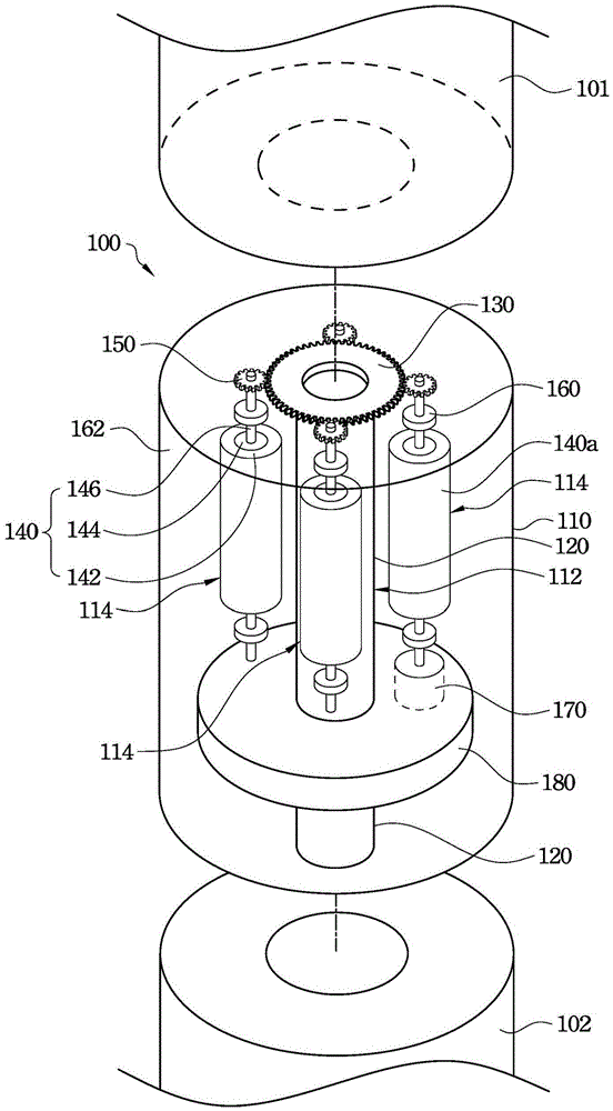
[0067] refer to figure 1 , which shows a perspective view of an embodiment of the mechanical joint of the present invention. The mechanical joint 100 includes a casing 110 , a hollow shaft 120 , a first gear 130 , a plurality of motors 140 and a plurality of second gears 150 . The casing 110 includes a first cavity 112 for accommodating the hollow shaft 120 and a plurality of second cavities 114 for accommodating the motor 140 . The second cavities 114 are disposed around the first cavity 112 . The cross-sectional shapes of the first hole 112 and the second hole 114 are circular, and the cross...


PUM


Abstract

The invention discloses a mechanical joint and a robot arm comprising the mechanical joint. The mechanical joint comprises a hollow shaft, a first gear, a plurality of motors, a plurality of second gears, an encoder and a digital processing and driving unit. The first gear is fixed to the hollow shaft. The motors surround the hollow shaft and are respectively provided with a rotating shaft. The second gears are fixed to the rotating shafts and meshed with the first gear. The motors drive the second gears to rotate the hollow shaft. The encoder is arranged at the side, opposite to the corresponding second gear, of one motor. A signal of the encoder is transmitted back to the digital processing and driving unit to drive the motors. According to the mechanical joint, as the motors drive the hollow shaft to rotate in cooperation with the gears, output torsion of the hollow shaft can be effectively increased, and magnitude of deceleration is lowered. A user can adjust the number of the motors according to different requirements to change torsion and rotating speed of the hollow shaft of the mechanical joint. Due to the fact that the encoder and the digital processing and driving unit are located on the same plane, space allocation can be effectively saved.

Description

technical field [0001] The invention relates to a mechanical joint, in particular to a mechanical joint applied to a mechanical arm. Background technique [0002] The robot arm (robotarm) is an automatic control device that imitates the function of the human arm and can complete various tasks. This robot system is multi-jointed and allows movement in a plane or three-dimensional space or using linear displacement. Structurally, it is composed of a mechanical body, a controller, a servo mechanism and a sensor, and a certain specified action is set by a program according to the operation requirements. For example, the servo mechanism can be used to drive the mobile robot arm to the position, and then perform the action of the clamp, and accurately feed back to the programmable logic controller. [0003] Most of the robotic arms are mainly aimed at completing the movements of the wrist and hand. After inputting the operation sequence into the controller, it can repeat countles...

Claims


Application Information

Patent Timeline
Patent Type & Authority Patents(China)
IPC IPC(8): B25J17/02B25J9/00B25J13/00
Inventor 蔡清雄
Owner DELTA ELECTRONICS INC
Learn More