Direct-current brush gear motor

A deceleration motor, DC brush technology, applied in the direction of electromechanical devices, electrical components, electric components, etc., can solve the problems affecting the service life of the reducer, abnormal collision noise, etc., to improve the starting response speed, service life and convenience sexual effect

Pending Publication Date: 2022-07-22
常州迈特运控电机有限公司
View PDF0 Cites 2 Cited by
  • Summary
  • Abstract
  • Description
  • Claims
  • Application Information

AI Technical Summary

Problems solved by technology

[0004] In view of the above-mentioned related technologies, the inventor believes that during the reversing process of the reducer of the related electric power steering system, when the EPS motor stops providing driving force to the worm, the worm gear will exert a force on the worm under the action of rotational inertia along the axial direction of the worm. Under the action of inertial force, the worm will drive the rotor of the EPS motor to move axially, and there will be abnormal collisions with the motor casing, etc., which will affect the service life of the reducer

Method used


Image

  • Direct-current brush gear motor
  • Direct-current brush gear motor
  • Direct-current brush gear motor

Examples


Embodiment 1

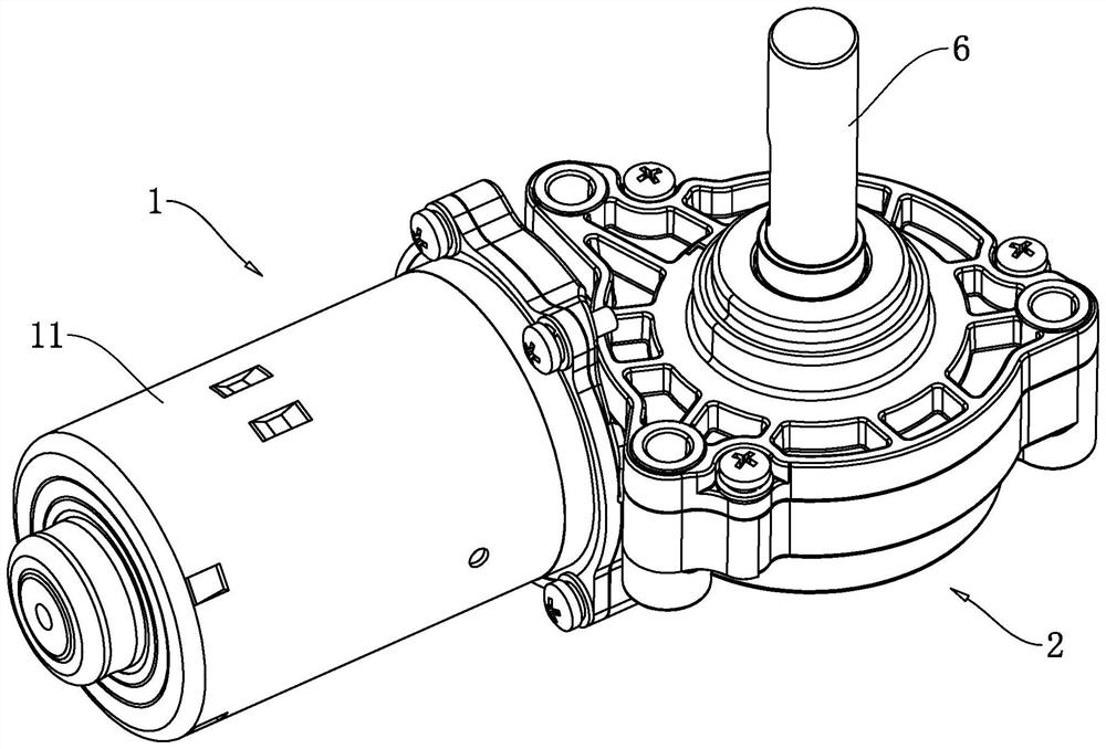
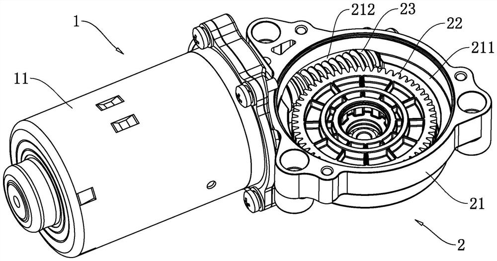
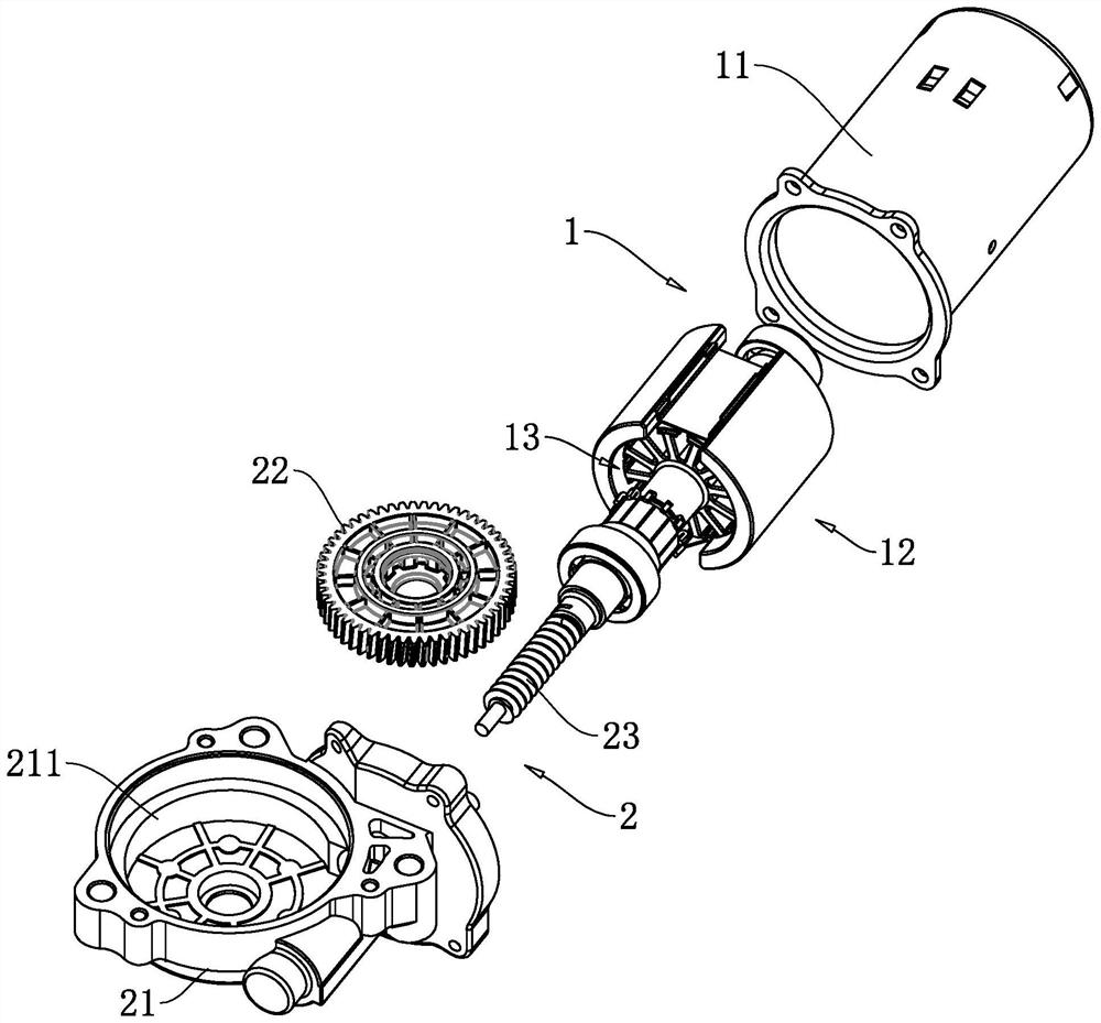
[0043] The embodiment of the present application discloses a DC brushed deceleration motor. refer to figure 1 , figure 2 and image 3 , a DC brush deceleration motor includes a drive motor 1 , a deceleration mechanism 2 and an output shaft 6 . The drive motor 1 includes a casing 11 and a stator 12 and a rotor 13 installed in the casing 11, and the deceleration mechanism 2 includes a casing 21, a worm gear 22 and a worm 23; the casing 11 is bolted to one side of the casing 21, The box body 21 is provided with a first installation cavity 211 for installing the worm 23 and a second installation cavity 212 for the worm 23 to be installed. The first installation cavity 211 and the second installation cavity 212 communicate with each other. The worm wheel 22 is located in the first installation cavity 211 and is rotatably connected with the box body 21 , the worm 23 is passed through the second installation cavity 212 of the box body 21 , the worm wheel 22 is engaged with the wo...

Embodiment 2

[0055] refer to Figure 9 and Figure 10 The difference between the embodiment of the present application and the embodiment 1 is that: the box body 21 is provided with a center distance fine-tuning mechanism 5, and the center distance fine-tuning mechanism 5 includes a mounting seat 51, a mounting ring 52, a third bearing 53 and an adjusting bolt 54, A connecting groove 214 is defined on the inner wall of the second mounting cavity 212 , the mounting seat 51 is fixed in the connecting groove 214 , and a circular through hole is defined in the center of the mounting seat 51 . The mounting ring 52 is located in the port, and the mounting ring 52 is coaxially arranged with the port. A fine-tuning gap 55 is formed between the outer wall of the mounting ring 52 and the inner wall of the port, and the fine-tuning gap 55 is 1.5mm-2.5mm. , the fine adjustment gap 55 is set to 2mm. An elastic connecting block 56 is connected between the mounting ring 52 and the mounting seat 51 , th...


PUM


Abstract

The invention relates to a direct-current brush gear motor, and relates to the field of gear motors, the direct-current brush gear motor comprises a driving motor and a speed reducing mechanism, the driving motor comprises a casing, and a stator and a rotor arranged in the casing; the speed reducing mechanism comprises a box body, a worm gear and a worm, the machine shell is connected to one side of the box body, the worm gear is rotationally connected into the box body, the worm penetrates through the box body, and the worm is meshed with the worm gear and connected with the output end of the rotor; an axial limiting structure is arranged on the worm, the axial limiting structure comprises a first limiting piece and a second limiting piece, the first limiting piece and the second limiting piece are both fixed relative to the worm, the first limiting piece abuts against the inner side wall of the box body, and the second limiting piece abuts against the outer side of the box body. The situation that in the rotating reversing process of the speed reducer, the worm axially moves under the action of the rotating inertia force of the worm gear, and then collision abnormal sound is caused is effectively reduced, the running stability and reliability of the speed reducer are guaranteed, and the service life is prolonged.

Description

technical field [0001] The present application relates to the field of geared motors, in particular to a DC brushed geared motor. Background technique [0002] The electric power steering system is based on the ECU controller to control the rotation of the EPS motor according to the changes of the sensor torque signal and angle signal collected, and the EPS motor drives the worm gear-worm reduction mechanism to provide the assistance required for the vehicle steering, thereby improving the steering performance of the vehicle. . That is, the EPS steering system is used to improve the motion stability of the vehicle by utilizing the power of a separate EPS motor to assist the steering of the vehicle. Traditionally, the auxiliary steering device used hydraulic pressure, but recently, from the viewpoints of reducing engine load, reducing weight, improving steering stability, and quick restoring force, the use of gears adapted to transmit the rotational output of the motor via a...

Claims


Application Information

Patent Timeline
Patent Type & Authority Applications(China)
IPC IPC(8): H02K7/116H02K5/24H02K5/16H02K5/04H02K1/17H02K1/26
CPCH02K7/1166H02K5/24H02K5/16H02K5/04H02K1/17H02K1/26
Inventor 任冬冬温玉峰温涛
Owner 常州迈特运控电机有限公司
Why Eureka
Try Eureka