Permanent magnetism biased radial magnetic bearing in external rotor

A technology of permanent magnetic bias and external rotor, applied in the direction of bearings, shafts and bearings, shafts, etc., can solve the problems of severe coupling, large excitation current, multi-magnetomotive force, etc., so as to ensure the stability of operation and reduce the axial Size, effect of saving control circuit

Inactive Publication Date: 2006-11-22
BEIHANG UNIV
View PDF0 Cites 3 Cited by
  • Summary
  • Abstract
  • Description
  • Claims
  • Application Information

AI Technical Summary

Problems solved by technology

However, the current permanent magnet bias external rotor radial magnetic bearing structure mainly has the following types: one is to place permanent magnets on the electromagnetic magnetic circuit on the basis of ordinary radial electromagnetic bearings, so that the magnetic flux generated by the control coil needs to be Through the interior of the permanent magnet, because the permanent magnet has a large reluctance, the control coil needs a large excitation current to generate a certain electromagnetic flux. The second is to connect the permanent magnet directly to the stator laminated core, so that the permanent magnetic circuit Excessive magnetomotive force will be lost when passing through the stator core, which will greatly weaken the attraction force of the permanent magnet to the rotor shaft. The third is that a stator core forms 4 magnetic poles, and 2 stator cores form 8 magnetic bearings at the left and right ends. Magnetic poles, each stator core is wound with a coil, the rotor core is connected through the outer magnetic ring, the inside of the rotor core is the stator core, and there is a certain air gap between the inner surface of the rotor core and the outer surface of the stator core, and the inner magnetic ring is installed on the Inside the stator core, the permanent magnet is located in the middle of the two inner magnetic rings, and the two inner magnetic rings connect the left and right ends of the stator core to form a magnetic path. This structure can make the electric excitation magnetic circuit not pass through the permanent magnet, and avoid The permanent magnet is directly connected to the laminated stator core, but due to the serious coupling of the electric excitation magnetic circuit in the X direction and the Y direction, it will make the control of the magnetic bearing more difficult.
In view of the above reasons, the existing permanent magnet bias outer rotor radial magnetic bearing has the disadvantage of severe coupling in the X direction and the Y direction

Method used


Image

  • Permanent magnetism biased radial magnetic bearing in external rotor
  • Permanent magnetism biased radial magnetic bearing in external rotor

Examples


Embodiment Construction

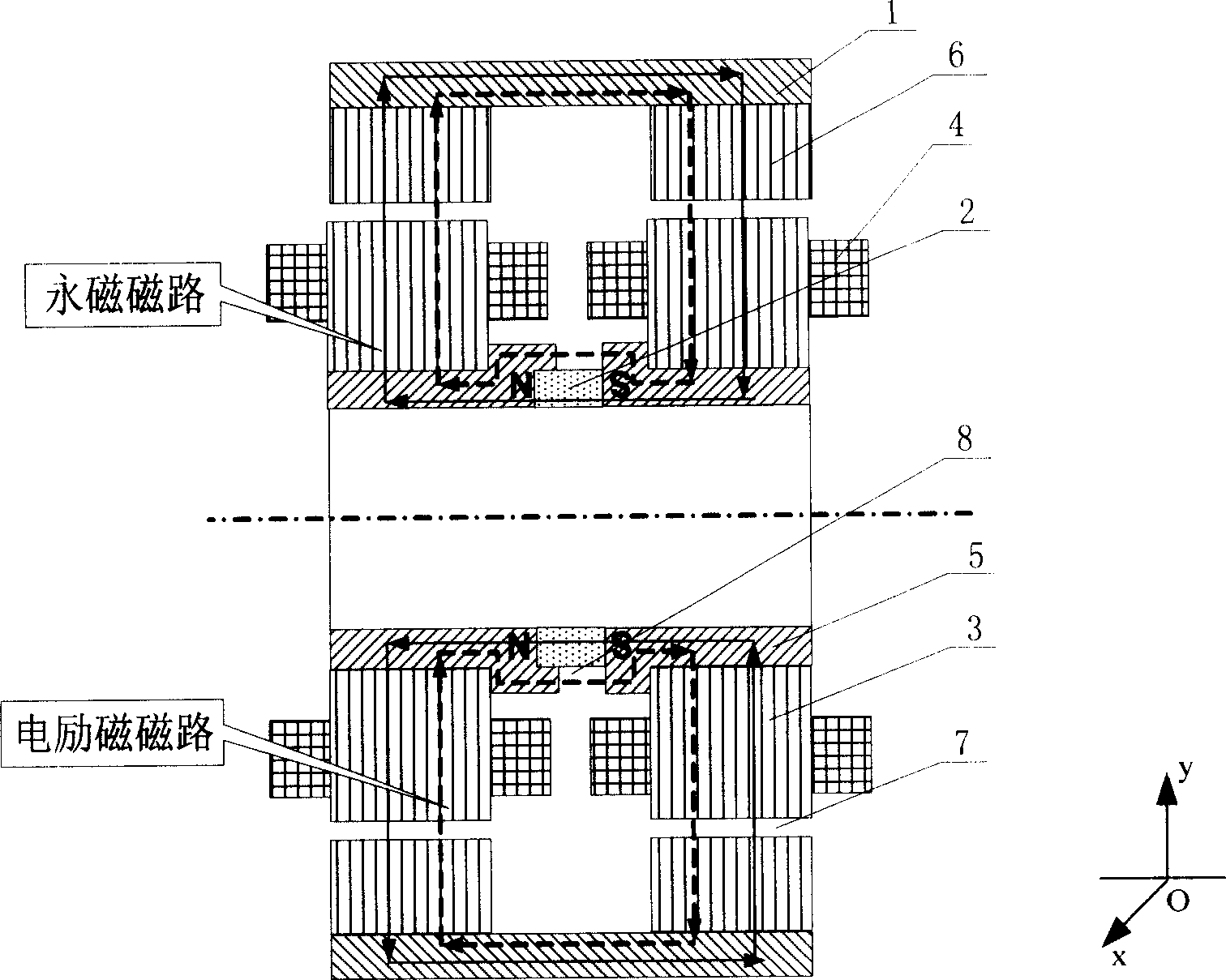
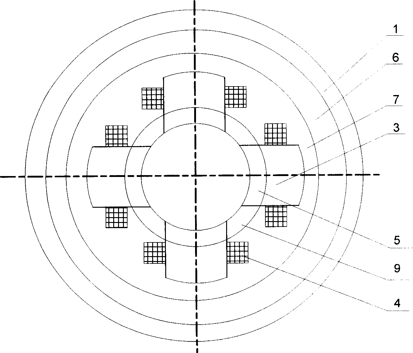
[0010] Such as figure 1 , 2 As shown, the present invention consists of 1 outer magnetic guide ring 1, 1 permanent magnet 2, 8 stator cores 3, 8 inner spacer magnets 9, 8 excitation coils 4, 8 inner guide magnets 5, 2 rotors 6 iron cores, 4 stator cores 3 form 4 stator poles in the X and Y directions, 8 stator cores 3 form the stator poles in the X and Y directions at the left and right ends of the magnetic bearing, and 8 inner spacer magnets 9 connect The stator core 3 at the left and right ends of the magnetic bearing in the X and Y directions, each stator pole is wound with an excitation coil 4, the outside of the stator core 3 is the rotor core 6, the outside of the rotor core 6 is the outer magnetic ring 1, and the inside of the rotor core 6 There is a certain gap between the surface and the outer surface of the stator core 3 to form an air gap 7. The permanent magnet 2 is located between the inner magnets 5, and a second air gap 8 is formed between the inner magnets 5 a...


PUM


Abstract

The invention is the permanent magnet offset outside rotor axial magnetic bearing, which comprises the outside magnetizing ring, the permanent magnet, the stator iron core, the inner blocking magnet, the excitating coil, the inner magnetizer and the rotor iron core. Four stator iron cores compose the four stator magnetic poles in X and Y positive and negative directions and are connected by the inner magnetizer and inner blocking magnet; eight stator iron cores compose the eight magnetic poles at two ends of the magnetic bearing, and every stator magnetic pole is wound by the coil; the rotor iron core is outside of the stator iron core; the outside magnetizing ring is outside of the rotor iron core; the outside magnetizing ring connects the rotor iron core, the inner surface of the rotor iron core and the outer surface of the stator iron core have the clearance between them and form the air clearance; the permanent magnet is between the inner magnetizing; the inner magnetizer and the permanent magnet form the second air clearance to form the electric circuit. The invention solves the problem of the prior art and has reliable stability.

Description

Technical field [0001] The invention relates to a non-contact magnetic suspension bearing, in particular to a permanent magnetic bias outer rotor radial magnetic bearing, which can be used as a non-contact support for rotating parts in mechanical equipment such as motors and machine tools. Background technique [0002] Magnetic suspension bearings are divided into pure electromagnetic bearings and hybrid magnetic suspension bearings with permanent magnetic bias and electromagnetic control. The former uses large current and consumes a lot of power, and the hybrid magnetic suspension bearings with permanent magnetic bias and electromagnetic control. The magnetic field generated by the permanent magnet bears the main load. Bearing capacity, the electromagnetic field provides auxiliary adjustment bearing capacity, so this kind of bearing can greatly reduce the control current and reduce the loss. However, the current permanent magnet bias external rotor radial magnetic bearing s...

Claims


Application Information

Patent Timeline
Patent Type & Authority Patents(China)
IPC IPC(8): F16C32/04H02K7/09
CPCF16C32/0465F16C32/0487F16C2300/20
Inventor 孙津济房建成马善振
Owner BEIHANG UNIV
Why Eureka
Try Eureka