Connecting Mechanism for Wind Power Plant

A technology of wind power generation device and connecting mechanism, which is applied to wind turbines, wind turbine combinations, wind energy power generation and other directions, can solve the problems of high wind utilization rate and low utilization rate at low altitude, and achieves high power generation efficiency, improved effect and good flexibility. Effect

Inactive Publication Date: 2016-08-17
大唐桂冠招远电力投资有限公司
View PDF3 Cites 0 Cited by
  • Summary
  • Abstract
  • Description
  • Claims
  • Application Information

AI Technical Summary

Problems solved by technology

Traditional wind turbines have a large utilization rate of wind power at high altitudes, but a small utilization rate of wind power at low altitudes

Method used


Image

  • Connecting Mechanism for Wind Power Plant
  • Connecting Mechanism for Wind Power Plant
  • Connecting Mechanism for Wind Power Plant

Examples


Embodiment 1

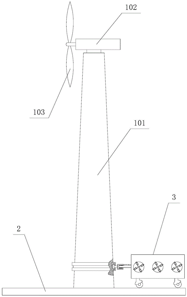
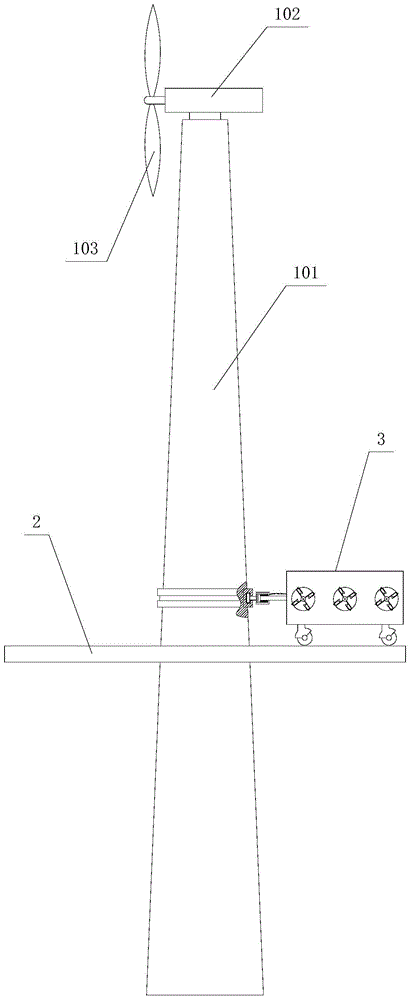
[0034] Embodiment 1, an annular locking groove 1011 is provided on the side wall of the column 101, and a locking block 45 is provided at the end of the sleeve 41, and the locking block 45 is slidably fitted in the annular locking groove 1011; the cross section of the annular locking groove is T-shaped, correspondingly, the longitudinal section of the clamping block 45 is also T-shaped; in order to prevent abrasion, improve the lubricating performance, and prevent from being stuck when sliding, a pressing plate 46 is provided between the clamping groove 1011 and the end surface of the clamping block 45, The pressing plate is made of self-lubricating material, preferably graphite or polytetrafluoro material.

Embodiment 2

[0035] In the second embodiment, a circular ring is provided, and the circular ring is rotatably set on the side wall of the column 101 through a bearing, and the sleeve 41 is fixedly connected to the circular ring to realize rotation around the column.

[0036] In order to improve the stability performance, there are two connecting rods and they are located in the same horizontal plane.

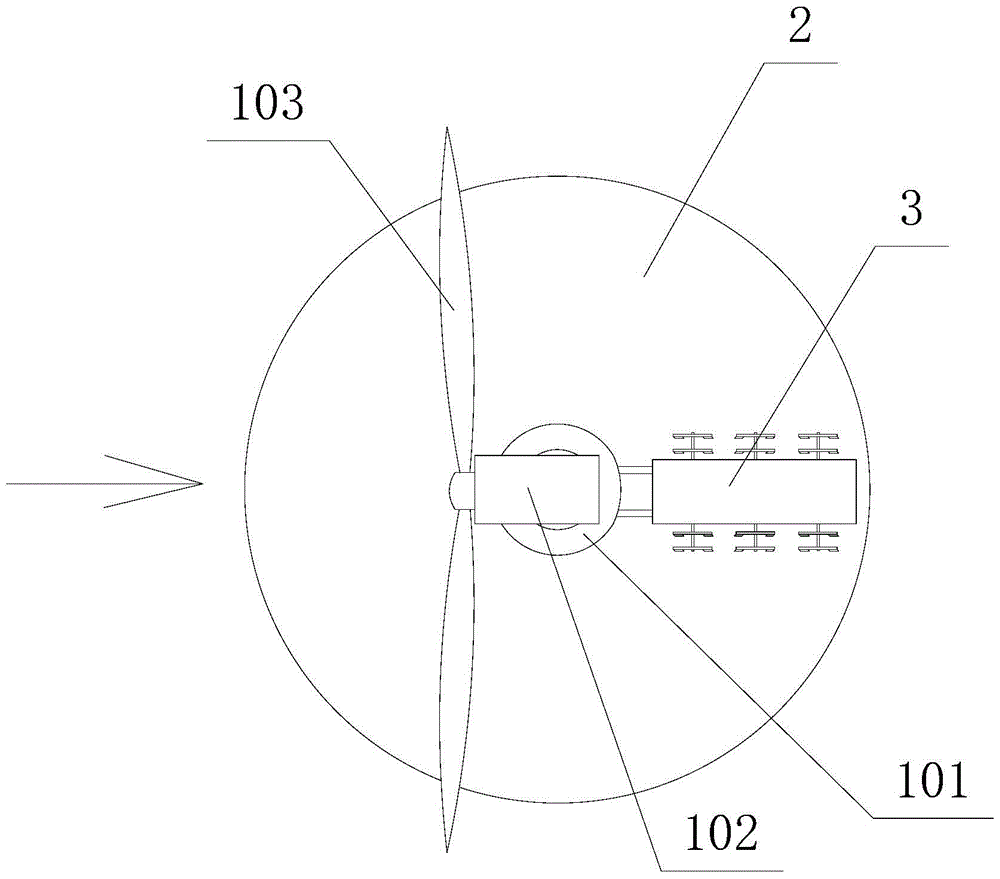
[0037] The present invention also provides a wing wheel structure, and the specific structure is as follows: a fixed shaft sleeve 3031 with a central hole is provided, a keyway for radial positioning is provided in the central hole of the fixed shaft sleeve 3031, and the side wall of the fixed shaft sleeve 3031 There are at least three wing shafts 3032 evenly distributed in the circumferential direction, preferably four, and two blades 3033 facing the same direction are rotatably installed on each wing shaft 3032, and the rotation angle of each blade 3033 is less than or equal to 90 degrees, ...


PUM


Abstract

The invention provides a connecting mechanism of a wind power generation device. The connecting mechanism of the wind power generation device comprises a stand column, a base and a shell. The base is fixed to the bottom of the stand column or arranged on the stand column in a sleeved mode. The shell is placed on the base in a sliding mode. A connecting rod is arranged between the shell and the stand column and comprises a sleeve and a pull rod, one end of the pull rod is arranged in the sleeve in a sliding fit mode, and the other end of the pull rod is connected to the shell. An elastic component making the pull rod have the opposite motion trend is arranged in the sleeve, and the sleeve is connected to the side wall of the stand column and can make circumferential motion on the side wall of the stand column. The connecting mechanism of the wind power generation device is high in power generation efficiency, good in flexibility and capable of moving independently in different directions; because wind power at the high altitude and wind power at the lower altitude can be utilized at the same time, the space utilization rate is good; a manmade air suction protection forest can be formed, and thus the sand stabilization effect is improved; a brake cable can be automatically tensioned when the wind speed is too high, and thus the safety coefficient is high.

Description

technical field [0001] The invention relates to a power generating device, in particular to a connection mechanism of a wind power generating device. Background technique [0002] Deserts are the main killer of global warming and gas emissions are only an accomplice. my country has 2 million square kilometers of desert. Sand control is a daunting task for generations. Sand control projects are not only our own interests but also the interests of all mankind. In general, there are two ways to control deserts. One is direct sand control. The second is indirect sand control. The existing sand control methods all belong to the direct sand control method, and the flow of sand is the effect of wind. Reduce the speed of the wind and the sand will lose its power. Combined with direct sand fixation on the basis of sand fixation, the ultimate goal is to make the desert green. To control sand, we must first control wind. How to control the wind is the key. Traditional wind tur...

Claims


Application Information

Patent Timeline
Patent Type & Authority Patents(China)
IPC IPC(8): F03D80/00F03D9/00
CPCY02E10/72
Inventor 刘金光程宪奎
Owner 大唐桂冠招远电力投资有限公司
Why Eureka
Try Eureka