Device for improving energy conversion efficiency of air compressor

A technology of energy conversion efficiency and air compressors, which is applied in the direction of pump devices, mechanical equipment, machines/engines, etc., can solve the problems of wasting electric energy, adverse effects on the service life of air compressors and motors, and high maintenance costs, so as to reduce frequent The effect of starting and unloading, improving energy utilization efficiency, and avoiding frequent starting and stopping

Inactive Publication Date: 2014-04-16
金华金翎科技服务有限公司
View PDF5 Cites 2 Cited by
  • Summary
  • Abstract
  • Description
  • Claims
  • Application Information

AI Technical Summary

Problems solved by technology

However, they have the following technical defects: the instrument air compressor device, the nitrogen air compressor device and the compressed air device for production cannot share the compressed air source between each other, and the three sets of devices often need to be operated at the same time, and when a certain When the air pressure output by the air supply system of the device meets the requirements, the air compressor motor of the device is unloaded, but the motor is still in an idling state for a period of time, and the motor is frequently started and unloaded to waste electric energy; the motor starts and stops frequently, and the current is large when starting. The impact on the power grid is large, and it also has an adverse effect on the service life of the air compressor and the motor; multiple devices run at the same time, and the energy consumption is high
Loud noise and high equipment maintenance costs

Method used


Image

  • Device for improving energy conversion efficiency of air compressor

Examples


Embodiment Construction

[0012] The present invention will be further described below in conjunction with the accompanying drawings and embodiments. While the invention will be described in conjunction with the preferred embodiments, it will be understood that it is not intended to limit the invention to the described embodiments. On the contrary, the invention is to cover alternatives, modifications and equivalents, which may be included within the scope of the invention as defined by the appended claims.

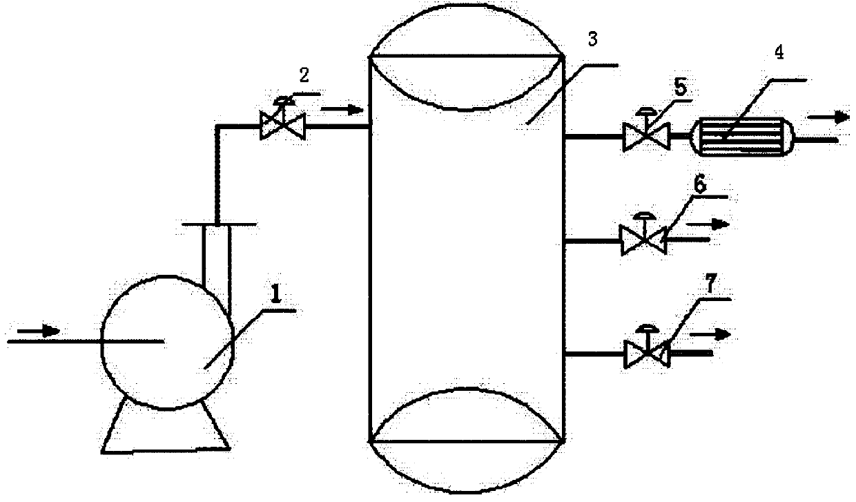
[0013] refer to figure 1 , this embodiment includes an air compressor 1, a drying device 4, and a gas storage device 3. The gas storage device 3 is cylindrical, and a drain valve, a manhole, a safety valve and a pressure gauge are arranged on it (not shown in the figure) , the manhole is on the tank body of the gas storage device 3, and the drain valve, safety valve and pressure gauge are connected to the gas storage device 3 through pipelines; 1. It is connected to the gas storage device 3 thro...


PUM


Abstract

The invention discloses a device for improving the energy conversion efficiency of an air compressor. The device for improving the energy conversion efficiency of the air compressor comprises the air compressor, drying equipment and air storage equipment, wherein the air storage equipment is provided with an air inlet channel and an air supply channel; the air inlet channel is provided with a first valve; the air supply channel is provided with a second valve, a third valve and a fourth valve; the air compressor is connected with the air storage equipment through the air inlet channel; the air supply channel is connected with an instrument air consuming system by connecting the second valve and the drying equipment; and the valves are respectively connected with a nitrogen generation system and a production air consuming system via two pipes. The device for improving the energy conversion efficiency of the air compressor has the advantages that the device is operated flexibly, three air compressor units comprising the instrument air consuming system, the nitrogen generation air consuming system and the production process air consuming system are integrated into an air compressor unit, the energy using efficiency of the systems is improved, frequent starting and unloading of a motor are avoided, electric energy is saved, the problems that the motor of the air compressor unit is started or stopped frequently, and starting current is high, so that a power grid is impacted are solved, and running noise of an air compression station and repair cost for equipment are reduced.

Description

technical field [0001] The invention relates to a device for improving energy conversion efficiency, more specifically, it relates to a device for improving energy conversion efficiency of an air compressor. Background technique [0002] According to the inspection by authoritative organizations, only 10% of the electric energy consumed by the air compressor is converted into compressed air, and the remaining 90% is converted into heat energy. It can be seen that compressed air is ten times more expensive than electricity, but we often ignore it. at this point. In most factories, the sound of air leakage can be heard everywhere, but no one pays attention to it at all. If we solve the leakage problem, we will save a lot of energy. Therefore, when we hear the air leakage, we must take timely measures measures. There are also some factories that have great misunderstandings in the way of using gas. For example, in circuit board manufacturers, most electroplating lines use vib...

Claims


Application Information

Patent Timeline
Patent Type & Authority Applications(China)
IPC IPC(8): F04B41/02F04B39/00
Inventor 胡井冈
Owner 金华金翎科技服务有限公司
Why Eureka
Try Eureka