An anti-icing isolation valve

An isolation valve and anti-icing technology, applied to valve devices, cocks including cut-off devices, fluid pressure actuators, etc., can solve the problems of increasing initial pipeline laying costs, increasing leakage and corrosion, and consuming large electric energy, etc., and achieve reduction The effect of protection and explosion-proof grade requirements, cost saving, and improvement of reliability and stability

Active Publication Date: 2016-05-18
CHENGDU ZHONGHUAN FLOW CONTROLS MFG
View PDF10 Cites 0 Cited by
  • Summary
  • Abstract
  • Description
  • Claims
  • Application Information

AI Technical Summary

Problems solved by technology

However, this treatment method has the following problems: firstly, it increases the initial pipeline laying cost; secondly, the electric heating method consumes a large amount of electric energy, and has a high failure rate. "Faults still happen; in the end, the start and stop of heat tracing is usually realized by temperature monitoring, which is costly and low reliability
In addition, since the natural gas is directly transmitted to the pressure detection port of the safety control cabinet along the natural gas pressure transmission monitoring pipeline, the highly toxic and corrosive components such as hydrogen sulfide contained in the natural gas also increase the risk of leakage and corrosion during long-distance transmission. At the same time, natural gas is a flammable and explosive gas. Therefore, laying heat tracing and heat preservation devices also puts forward higher protection and explosion-proof requirements for safety control cabinets, thus increasing costs.

Method used


Image

  • An anti-icing isolation valve
  • An anti-icing isolation valve
  • An anti-icing isolation valve

Examples


Embodiment Construction

[0017] In order to make the object, technical solution and advantages of the present invention clearer, the present invention will be described in detail below in conjunction with the accompanying drawings and specific embodiments. It should be understood that the specific embodiments described here are only used to explain the present invention, not to limit the present invention.

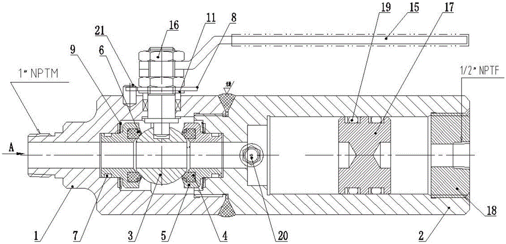
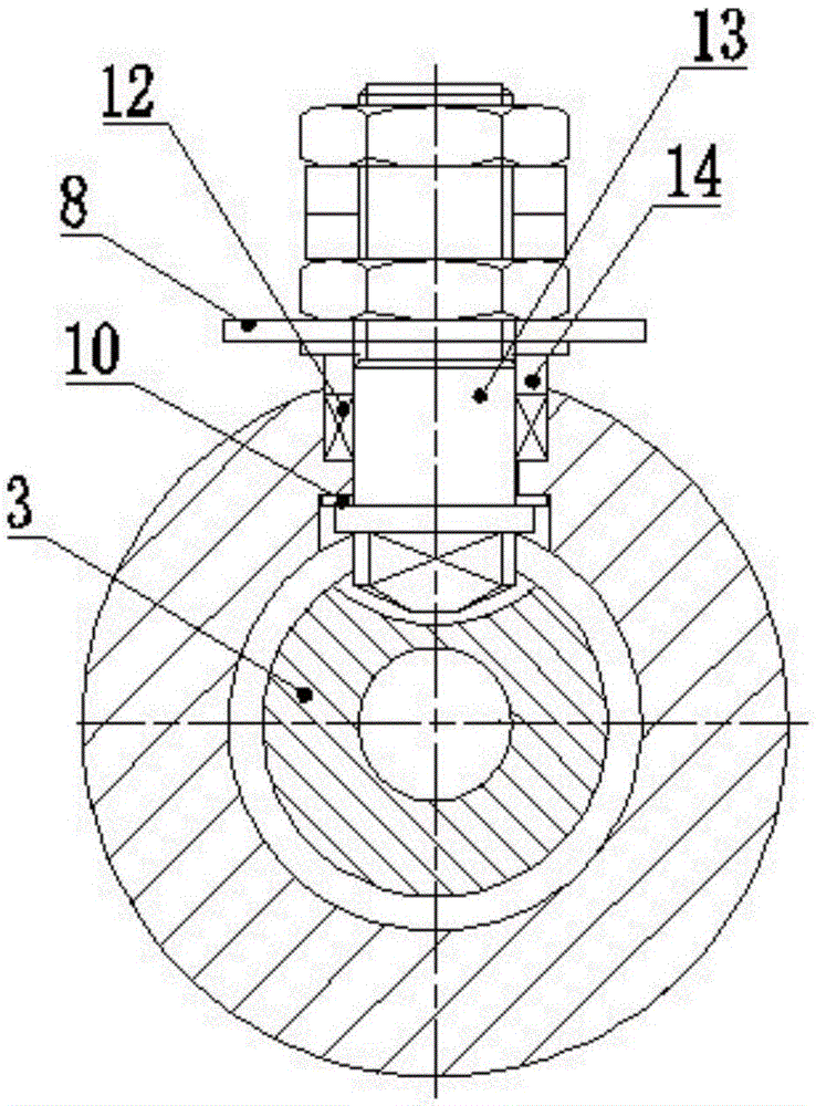
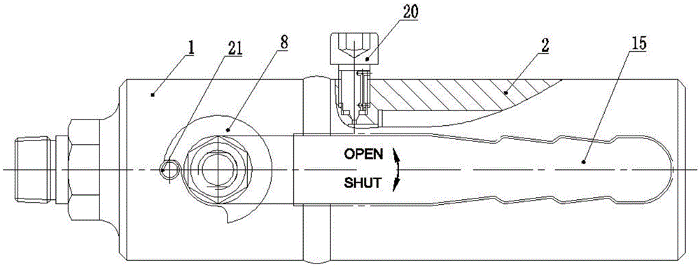
[0018] Such as Figure 1-Figure 3 The shown anti-icing isolation valve mainly includes a valve body 1, a cylinder body 2, a sphere with a through hole 3 and its radial sealing adjustment device, a valve seat 5, a valve stem 13 and its supporting sealing device. Wherein, the inner chamber of the cylinder body 2 is equipped with a piston 17 that can translate left and right, and the inlet end of the cylinder body 2 is welded and fixed to the outlet end of the valve body 1; 2 is provided with a threaded through hole communicating with the inner cavity of the cylinder body 2, and the cylinder body 2 ...


PUM


Abstract

The invention provides an ice blockage preventing isolation valve. The ice blockage preventing isolation valve comprises a valve body, a cylinder body, a ball body with a through hole, a radial sealing adjustment device for the ball body, valve bases, valve rods, and a supporting and sealing device for the valve bases and the valve rods, wherein the valve rods are fixedly connected with the ball body and control the ball body to rotate relative to the valve bases; the piston is mounted in an inner cavity of the cylinder body; the inlet end of the cylinder body is fixedly connected with the outlet end of the valve body; the two valve bases are arranged and symmetrically distributed at the both sides of the ball body by using the central axis of the ball body as the symmetry axis; one valve base is respectively connected with the radial sealing adjustment device for the ball body and the valve body; the other valve base is respectively connected with the cylinder body and the radial sealing adjustment device for the ball body; the supporting and sealing device for the valve rods are respectively connected with the valve body and the valve rods. The anti-ice blockage isolation valve can be used for effectively preventing from ice blockage which is caused by vapor is iced after being condensed and adhered to the inside of a pipeline, so that the difficult problem that the control function of a wellhead security control cabinet loses the efficiency due to low-temperature ice blockage of the pipeline can be basically solved; the ice blockage preventing isolation valve is beneficial to energy conversation, consumption reduction and cost saving.

Description

technical field [0001] The invention relates to the technical field of isolation valves, in particular to an isolation valve for preventing ice blockage. Background technique [0002] At present, in the wellhead safety control system of the gas tree, it is necessary to monitor the pressure of the natural gas at the wellhead for safety protection and automatic control. The conventional pressure sampling method is to combine the connection of pipelines, ball valves and conversion joints into a natural gas pressure transmission monitoring pipeline, and transmit the natural gas pressure at the pressure monitoring port of the natural gas wellhead directly from the wellhead to the pressure detection port of the wellhead safety control cabinet. Since the distance from the natural gas wellhead to the wellhead safety control cabinet is generally 20-50 meters, the natural gas just produced at the wellhead contains water vapor and the temperature is high (usually above 60°C, and some c...

Claims


Application Information

Patent Timeline
Patent Type & Authority Patents(China)
IPC IPC(8): F15B15/14F16K5/06
Inventor 李瑜贺洪波
Owner CHENGDU ZHONGHUAN FLOW CONTROLS MFG
Why Eureka
Try Eureka