Rocket engine spraying pipe motion vision measuring method and portable infrared light emitting device used in same

A rocket engine and visual measurement technology, applied in portable lighting devices, devices using optical methods, measuring devices, etc., can solve problems such as the inability to correctly identify cooperation targets, and achieve simple structure, improved measurement accuracy, and simple measurement steps Effect

Active Publication Date: 2014-04-16
HARBIN INST OF TECH
View PDF8 Cites 4 Cited by
  • Summary
  • Abstract
  • Description
  • Claims
  • Application Information

AI Technical Summary

Problems solved by technology

[0003] The present invention aims to solve the problem that the cooperative target cannot be correctly identified on the camera image plane due to the huge difference between the hot and cold test run of the rocket engine and the working conditions of the simulated nozzle when measuring the motion parameters of the nozzle of the rocket engine. problem, a method for visual measurement of rocket engine nozzle motion and a portable infrared light-emitting device used in the method are proposed

Method used


Image

  • Rocket engine spraying pipe motion vision measuring method and portable infrared light emitting device used in same
  • Rocket engine spraying pipe motion vision measuring method and portable infrared light emitting device used in same
  • Rocket engine spraying pipe motion vision measuring method and portable infrared light emitting device used in same

Examples


specific Embodiment approach 1

[0025] DETAILED DESCRIPTION OF THE PREFERRED EMBODIMENT One, a kind of rocket engine nozzle movement visual measurement method described in this specific embodiment comprises the following steps:

[0026] Step 1. Arranging a plurality of infrared luminescent points on the outer surface of the nozzle of the rocket engine,

[0027] Step 2, setting an infrared filter before the lens of the image acquisition device,

[0028] Step 3, connect the image acquisition signal output end of the image acquisition device with the image acquisition signal input end of the visual measurement system control computer,

[0029] Step 4. Aim the lens of the image acquisition device at the infrared light-emitting point,

[0030] Step 5, the image acquisition device performs image acquisition on a plurality of infrared light-emitting points on the outer surface of the nozzle of the rocket engine in motion, and sends the acquired images to the control computer of the visual measurement system,

[0...

specific Embodiment approach 2

[0032] Embodiment 2. The difference between this embodiment and the visual measurement method for rocket engine nozzle motion described in Embodiment 1 is that the infrared light-emitting point is realized by a portable infrared light-emitting device.

specific Embodiment approach 3

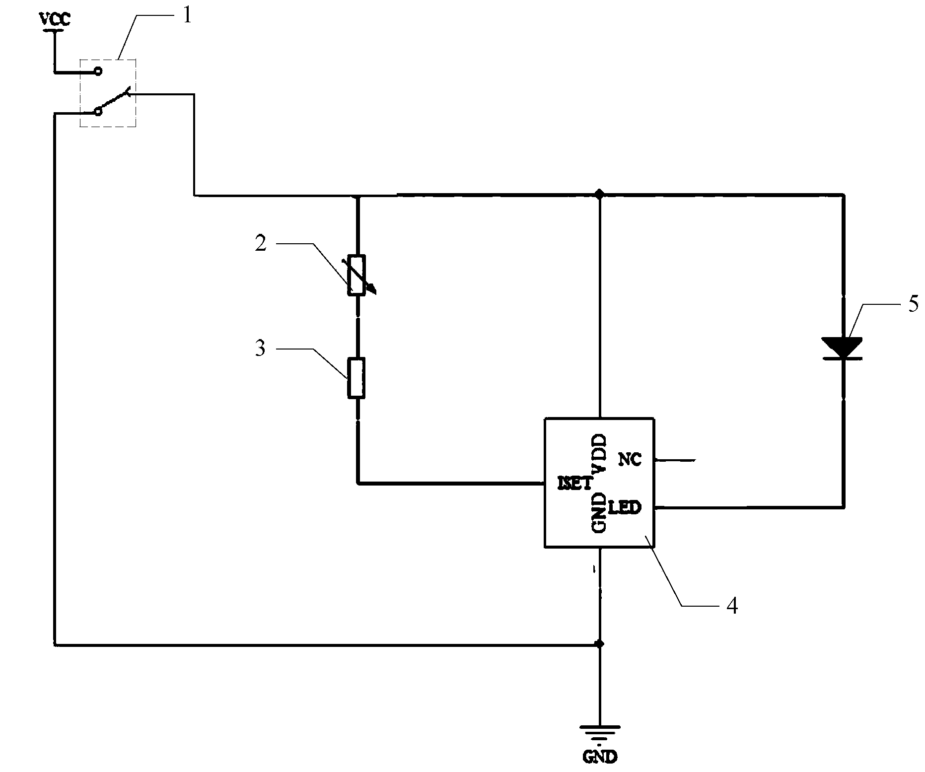
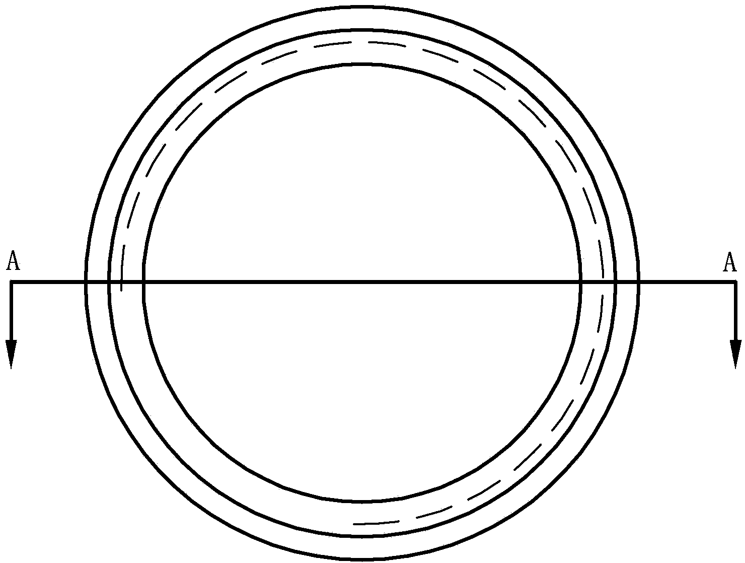
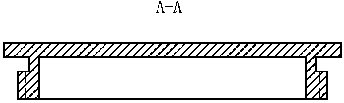
[0033] Specific embodiment three, combine Figure 1-Figure 10 Illustrate this specific embodiment, the portable infrared light-emitting device used in a kind of rocket engine nozzle motion visual measurement method described in specific embodiment 2 comprises infrared LED5, LED drive circuit and shell, and described LED drive circuit is used for driving infrared LED5 emits light, and the LED driving circuit is integrated on the circuit board and installed in the housing,

[0034] The LED drive circuit includes power supply VCC, fixed value resistor 3, adjustable resistor 2, constant current chip 4, toggle switch 1 and MiniUSB charging interface, one end of the adjustable resistor 2 is connected to the positive pole of the infrared LED5, and the other end of the adjustable resistor 2 One end is connected to one end of the fixed value resistor 3, the other end of the fixed value resistor 3 is connected to the constant current setting end of the infrared LED 5 of the constant cur...


PUM

PropertyMeasurementUnit
Resistanceaaaaaaaaaa
Diameteraaaaaaaaaa
Wavelengthaaaaaaaaaa

Abstract

The invention discloses a rocket engine spraying pipe motion vision measuring method and a portable infrared light emitting device used in same and relates to the rocket engine spraying pipe motion vision measuring field. The rocket engine spraying pipe motion vision measuring method and the portable infrared light emitting device used in the same solve the problem that a cooperative target cannot be correctly identified from a camera image plane due to the huge difference between a cold and hot trial running process and a simulated spraying pipe operating condition of the rocket engine when motion parameters of the rocket engine spraying pipe are measured. According to the rocket engine spraying pipe motion vision measuring method, a plurality of infrared luminous points are arranged on the outer surface of the rocket engine spraying pipe, an infrared optical filter is arranged before a lens of an image collecting device which collects images of the plurality of infrared luminous points which are arranged on the outer surface of the rocket engine spraying pipe, collected images are sent to a vision measuring system controlled computer, the rocket engine spraying pipe motion vision measuring purpose is achieved, and the infrared luminous points are achieved through a high luminance infrared light emitting device. The rocket engine spraying pipe motion vision measuring method is applicable to rocket engine spraying pipe motion vision measuring.

Description

technical field [0001] The invention relates to the field of visual measurement of rocket engine nozzle movement, in particular to the field of infrared light emitting devices in the visual measurement of rocket engine nozzle movement. Background technique [0002] The measurement of motion parameters (such as swing center and swing angle) of rocket engine nozzle is an important quality assurance for the attitude and trajectory control, range and landing accuracy of rockets and missiles. During the cold and hot test run of the existing rocket engine, the method adopted is to measure the angular displacement of the motion servo control rod with a rotary potentiometer, and then obtain the motion parameters of the nozzle through geometric conversion. This is an indirect measurement, and there is still a large measurement error. At present, the visual method of the cooperative target can realize the measurement of the motion parameters of the simulated nozzle. The cooperative t...

Claims


Application Information

Patent Timeline
IPC IPC(8): G01H9/00G01B11/26G01P3/38F21L4/00H05B37/02F21Y101/02F21Y115/10
CPCY02B20/42Y02B20/40
Inventor 郭玉波马惠萍于潇宇陈刚聂飞斌
Owner HARBIN INST OF TECH
Why Eureka
Try Eureka