
Laser measurement and positioning device and using method of wheel balancer

A technology of laser measurement and positioning device, which is applied in the direction of measuring device, static/dynamic balance test, machine/structural component test, etc. It can solve the problems that the unbalanced position cannot be accurately determined, and achieve the effect of simple operation and accurate measurement

Active Publication Date: 2014-04-16
科星汽车设备(珠海)有限公司
View PDF6 Cites 6 Cited by
  • Summary
  • Abstract
  • Description
  • Claims
  • Application Information

AI Technical Summary

Problems solved by technology

[0005] The main purpose of the present invention is to provide a laser measuring and positioning device for a wheel balancing machine that uses a laser to guide and paste lead weights at an accurate position and its use method, which can measure the parameters of the tire to be tested, and can also measure the different parts of the tire to be tested. The laser positioning of the balance position solves the problem that the unbalanced position cannot be accurately determined when the balance measurement of various wheels, especially the commonly used aluminum alloy wheels that cannot be balanced by external clamping, and realizes the automatic measurement of various tire parameters

Method used


Image

  • Laser measurement and positioning device and using method of wheel balancer
  • Laser measurement and positioning device and using method of wheel balancer
  • Laser measurement and positioning device and using method of wheel balancer

Examples


Embodiment Construction

[0026] It should be understood that the specific embodiments described here are only used to explain the present invention, not to limit the present invention.

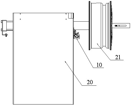
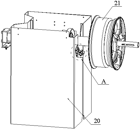
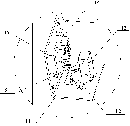
[0027] refer to Figure 1 to Figure 5 , propose an embodiment of the laser measuring and positioning device 10 of the wheel balancing machine of the present invention, the laser measuring and positioning device 10 of the wheel balancing machine includes a laser distance measuring device, a stepping motor 12, and a control module for controlling the stepping motor 12 14. The control panel and the microprocessor with sampling, calculation, storage and control functions, the signal output terminals of the control panel and the laser distance measuring device are respectively connected with the signal input terminal of the microprocessor, and the signal output terminal of the microprocessor is connected with the control Module 14 is connected to the signal input end of the laser distance measuring device. A control comma...


PUM


Abstract

The invention discloses a laser measurement and positioning device and a using method of a wheel balancer. The laser measurement and positioning device adopts a stepping motor to drive a laser transmitter to rotate till laser is pointed to the inner side edge of a measured tire, calculates an optical distance by utilizing the time from laser transmitting and laser receiving according to an optical principle so as to obtain a straight line distance from a laser head to a laser indication point, utilizes a geometrical mathematic model to calculate tire parameters according to an installing position constant of the laser measurement and positioning device, achieves automatic measurement of various tire parameters and is accurate in measurement and simple in operation. After tire balance calculation is finished, a microprocessor is adopted to convert a triangular side function formed by the detected unbalance position and an original point of the laser transmitter into an angle differential parameter and then sends an instruction to the stepping motor, the stepping motor drives the laser transmitter to rotate to a converted angle, and the laser transmitter enables the laser to be transmitted onto the unbalance position so as to achieve laser positioning of the unbalance position of the measured tire.

Description

technical field [0001] The invention relates to the field of tire balance detection, in particular to a laser measurement and positioning device of a wheel balancer and a method for using the same. Background technique [0002] If the wheels are unbalanced, the vibration of the steering wheel will cause the steering wheel to vibrate, which will affect the comfort of the driver. Moreover, it will also accelerate the wear of the axle and bearings, the wear of the suspension and steering system components, and the tire tread and the ground. It will cause abnormal wear and tear, which will seriously affect the service life of the tire. The most important thing is that it may involve personal safety at high speed, such as tire blowout, uncontrolled direction, rollover and so on. In order to solve the problem of unbalanced tires, people have manufactured a wheel balancer—a device used to measure the unbalanced amount of a car wheel and indicate the position of the unbalanced amoun...

Claims


Application Information

Patent Timeline
IPC IPC(8): G01M1/14
Inventor 杨海萍
Owner 科星汽车设备(珠海)有限公司
Learn More