Field test system and method for excitation device

An excitation device and on-site testing technology, which is applied in the direction of measuring devices, motor generator testing, measuring electricity, etc., can solve problems such as easy missing steps or data, lack of test demagnetization logic, and high requirements for test personnel, so as to achieve flexible configuration , Reduce requirements and test risks, simplify wiring and test operations

Active Publication Date: 2016-03-02
NARI TECH CO LTD
View PDF5 Cites 0 Cited by
  • Summary
  • Abstract
  • Description
  • Claims
  • Application Information

AI Technical Summary

Problems solved by technology

However, the user lacks a special debugging system for testing the de-excitation logic. The on-site test is very cumbersome and requires high requirements for the test personnel; when the excitation device is performing a functional simulation test, it needs to be connected to an external protection calibrator and other special equipment to input analog signals. It needs to be carried out step by step according to the operation steps. During the test, it is necessary to record data and record waveforms. After the test is completed, it is necessary to write a test report. It is easy to miss steps or data. These are difficult to meet the needs of modern power plants; in the no-load characteristics of generators When testing the short-circuit characteristics and short-circuit characteristics, it is necessary to connect a special instrument on the side of the excitation device to record data and store waveforms of the required machine terminal voltage and current, rotor voltage and current, and other signal quantities. The external wiring includes AC signals and DC signals of voltage and current. , on-site wiring is more troublesome

Method used


Image

  • Field test system and method for excitation device
  • Field test system and method for excitation device
  • Field test system and method for excitation device

Examples


Embodiment Construction

[0019] The technical scheme of the present invention will be described in further detail below in conjunction with the accompanying drawings and specific embodiments, so that those skilled in the art can better understand the present invention and implement it, but the examples given are not intended to limit the present invention.

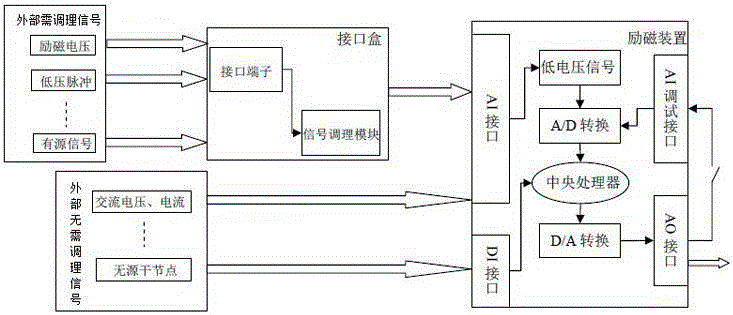
[0020] Such as figure 1 As shown, the excitation device on-site test system includes the excitation device, and the excitation device includes an AI interface, a DI interface, an AO interface and an AI debugging interface. Among them, the AI ​​interface is converted into a low-voltage signal and then performs A / D conversion and processing by the central processing unit. The DI interface directly enters the central processing unit for data processing. The AO interface outputs low-voltage or low-current signals from the central processing unit. The AI ​​debugging interface It directly receives the low-voltage signal, and then performs A / D conversion...


PUM


Abstract

A system and method for an on-site test of an excitation device. The system comprises an excitation device, wherein the excitation device comprises an AI interface, a DI interface, an AO interface and an AI debugging interface. It is characterized in that the system also comprises an interface box connected to the AI interface of the excitation device. The interface box comprises an interface terminal and a signal conditioning module which are connected to an external signal required to be coordinated. The signal conditioning module processes the external signal required to be coordinated and converts same into a signal which can be directly received by the AI interface. The AO interface is connected with the AI debugging interface via a soft switch. The system not only makes full use of the existing capability of the excitation device, but also simplifies wiring and test operations, so that analogue quantity and on-off quantity signals can be compatible at the same time, thereby realizing flexible configuration of input channels, and reducing requirements and test risks for on-site overhaul personnel. The present invention facilitates the early discovery of a possible hidden danger of a loop related to excitation, thus improving the overall reliability of the excitation device.

Description

technical field [0001] The invention relates to a field test system and method for an excitation device. Background technique [0002] The "Evaluation Standards for Grid-connected Safety of Generator Sets" stipulates that "the excitation system newly put into operation or after overhaul should be subjected to disturbance tests such as load shedding, step, zero-start voltage boost, and de-excitation according to national and industry standards. It should be able to reliably demagnetize the generator under various working conditions." Among them, in order to ensure the rapidity and reliability of demagnetization for large-scale units, the logic of the demagnetization circuit is often more complicated, and the timing requirements are stricter. In order to verify whether the demagnetization circuit meets the design requirements, it is necessary to measure dry nodes, low-voltage pulses, and high-voltage DC voltage at the same time. and other types of multi-channel signals. Howe...

Claims


Application Information

Patent Timeline
Patent Type & Authority Patents(China)
IPC IPC(8): G01R31/00G01R31/34
CPCG01R31/34
Inventor 许其品朱宏超袁亚洲王亚婧
Owner NARI TECH CO LTD
Why Eureka
Try Eureka