Organic light-emitting displayer and manufacturing method of organic light-emitting displayer

A light-emitting display and a technology of a manufacturing method, which are applied in the manufacture of semiconductor/solid-state devices, electric solid-state devices, semiconductor devices, etc., and can solve problems such as difficulty in aligning organic light-emitting elements 132 with light-transmitting openings, reducing reflectivity, and affecting image display effects, etc. , to achieve good mirror effect and image display effect, improve production yield, and ensure the effect of display effect

Inactive Publication Date: 2014-04-16
AU OPTRONICS CORP
View PDF0 Cites 8 Cited by
  • Summary
  • Abstract
  • Description
  • Claims
  • Application Information

AI Technical Summary

Problems solved by technology

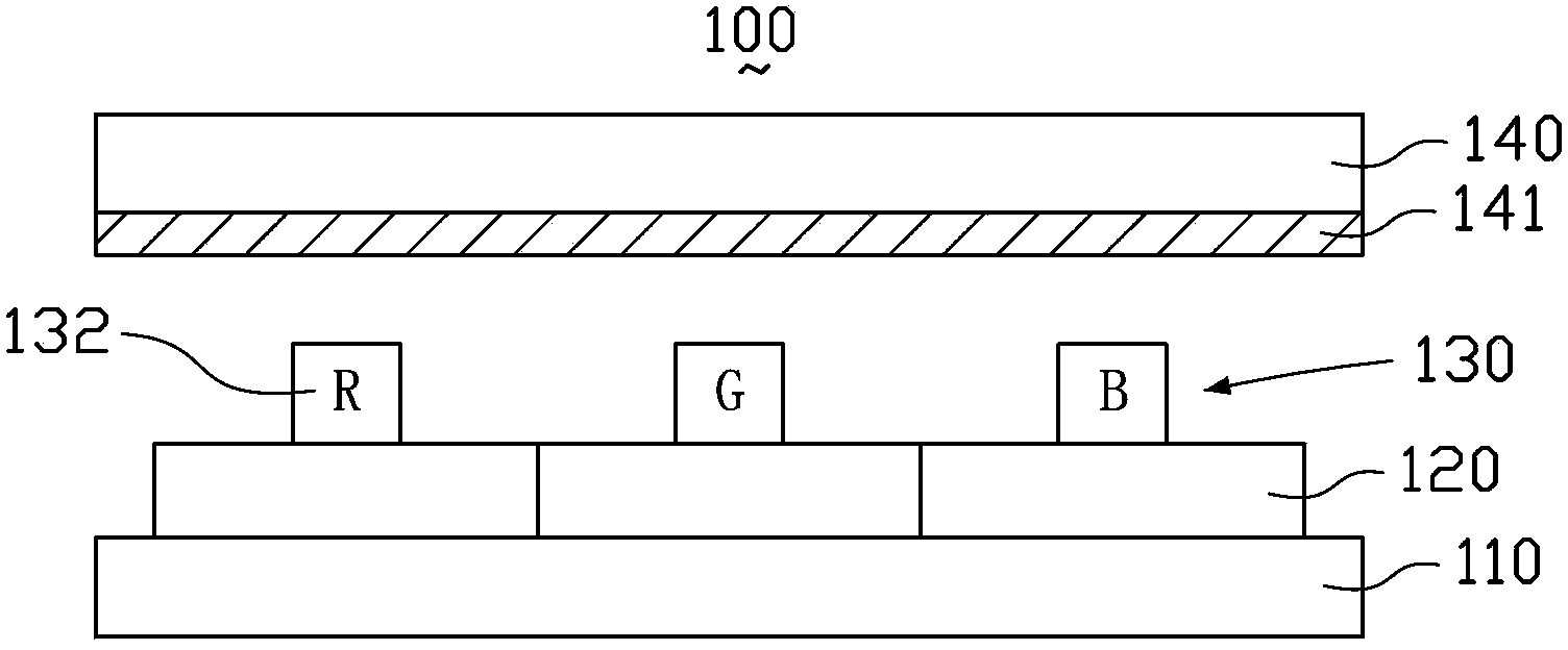
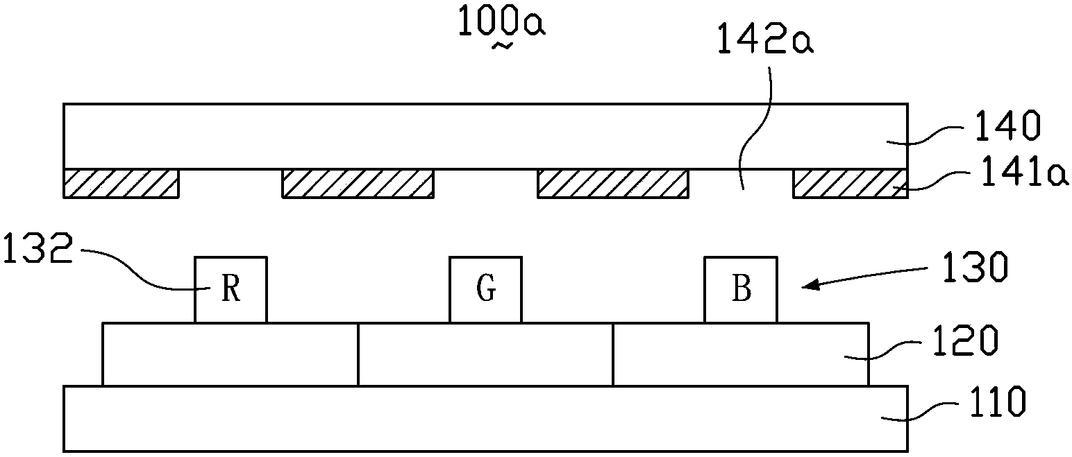
In theory, figure 2 and image 3 The OLED displays 100a and 100b have good mirror effects and image display effects at the same time, but in the actual manufacturing process, when the glass substrate 140 and the active element array substrate 110 are bonded and sealed, there will be light-transmitting openings 142a / 142b and Difficult Alignment of Organic Light Emitting Elements 132
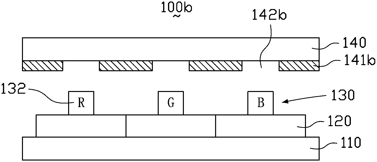
image 3 Although the OLED display 100b increases the size of the light-transmitting opening 142b of the glass substrate 140, although the alignment difficulty is reduced to a certain extent, the area of ​​the reflective film 141b is also reduced, which not only reduces the reflectivity and affects the mirror effect, It will also affect the image display effect
[0006] Therefore, the quality of the existing OLED display with mirror function needs to be improved urgently.

Method used


Image

  • Organic light-emitting displayer and manufacturing method of organic light-emitting displayer
  • Organic light-emitting displayer and manufacturing method of organic light-emitting displayer
  • Organic light-emitting displayer and manufacturing method of organic light-emitting displayer

Examples


Embodiment Construction

[0027] The embodiments of the present invention will be clearly and completely described below in conjunction with the accompanying drawings.

[0028] Figure 4 It is a schematic partial cross-sectional view of the organic light emitting display according to the first embodiment of the present invention. see Figure 4In this embodiment, the organic light emitting display 200 includes a driving element array substrate 210 and a glass substrate 270 disposed opposite to each other, and an organic light emitting element 230 and a reflective layer 250 disposed between the driving element array substrate 210 and the glass substrate 270 .

[0029] The driving element array substrate 210 includes a base 211 and a plurality of driving elements 212 ( Figure 4 Only one is shown), these driving elements 212 may be active elements such as thin film transistors. In this embodiment, in the process of manufacturing the driving element array substrate 210, a first conductive layer 2111, an...


PUM


Abstract

The invention relates to an organic light-emitting displayer which comprises a driving element array substrate, an organic light-emitting element layer and a reflecting layer. The organic light-emitting element layer comprises a first electrode layer, an organic light-emitting functional layer and a second electrode layer, the first electrode layer, the organic light-emitting functional layer and the second electrode layer are sequentially formed on the driving element array substrate, and a light outgoing area is defined by the organic light-emitting functional layer. The reflecting layer is located outside the light outgoing area of the organic light-emitting functional layer and arranged in the driving element array substrate, or the reflecting layer is located between the organic light-emitting element layer and the driving element array substrate, or the reflecting layer is located in the organic light-emitting element layer. The organic light-emitting displayer has the good mirror surface effect and the good image displaying effect at the same time. The invention further relates to a manufacturing method of the organic light-emitting displayer.

Description

technical field [0001] The invention relates to an organic light-emitting display, in particular to an organic light-emitting display with a mirror function and a manufacturing method thereof. Background technique [0002] Organic light-emitting diode (OLED) display, also known as organic electroluminescence display (OELD) or organic light-emitting display, compared with traditional liquid crystal display (liquid crystal display, LCD), does not require The additional light source (backlight) has excellent characteristics such as thinness, self-illumination, low power consumption, and wider viewing angle. It has been used in the display technology of electronic equipment, especially portable electronic equipment, and has received extensive attention. According to the driving method, the OLED display can be classified into an active matrix organic light emitting display (AMOLED) and a passive matrix organic light emitting display (PMOLED). According to the light emitting ...

Claims


Application Information

Patent Timeline
Patent Type & Authority Applications(China)
IPC IPC(8): H01L27/32H01L51/52H01L51/56
Inventor 周政伟
Owner AU OPTRONICS CORP
Why Eureka
Try Eureka