Lossless spiral conveying device

A technology of spiral transmission and spiral blades, which is applied in the field of conveying systems, can solve the problems of crop grain skin rupture, economic value decline, and damage to crop grains, etc., to achieve the effect of increasing completeness, ensuring cleanliness, and increasing conveying capacity

Inactive Publication Date: 2014-04-23
SHANDONG RUNYUAN IND
View PDF6 Cites 2 Cited by
  • Summary
  • Abstract
  • Description
  • Claims
  • Application Information

AI Technical Summary

Problems solved by technology

Because of the scraping action of the scraper or the high-speed agitation of the auger, the crop grains will inevitably be damaged during the transportation process, causing the skin of the crop grains to be broken or deformed, which will affect the quality of the harvested grains and cause their economic value to decline. , the market is difficult to sell

Method used


Image

  • Lossless spiral conveying device
  • Lossless spiral conveying device
  • Lossless spiral conveying device

Examples


Embodiment approach 1

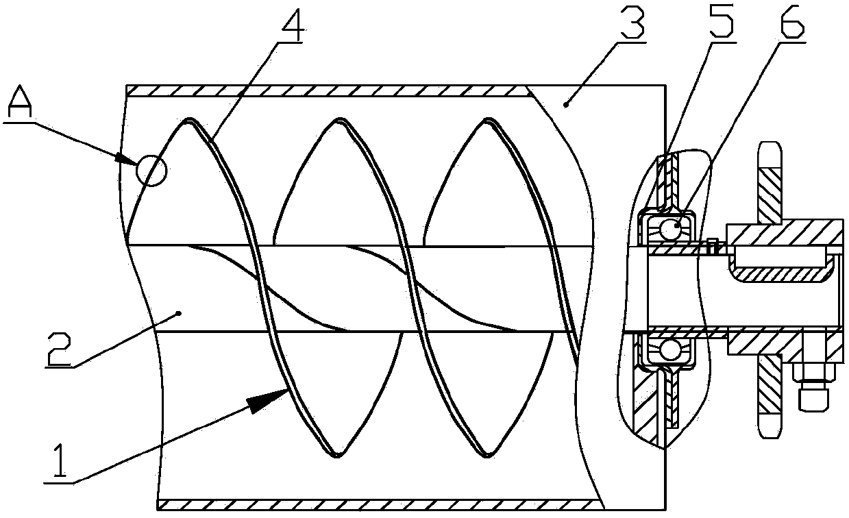
[0018] Such as figure 1 with figure 2 As shown, a non-destructive screw conveying device includes two or three conveying screw blades 1, a rotating shaft 2, a conveying tubular cavity 3, a flexible rubber layer 4, an annular protective cover 5 and a bearing 6.

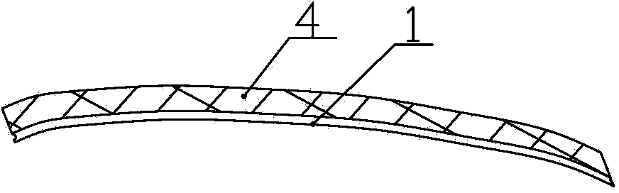
[0019] The rotating shaft 2 axially passes through the conveying tubular cavity 3 , and the two ends of the rotating shaft 2 are installed in bearing seats on the machine frame through bearings 6 . The conveying screw blade 1 is helically arranged on the outer wall of the rotating shaft 2 inside the conveying tubular cavity 3 . The flexible rubber layer 4 is detachably fixed at the edge of the conveying helical blade 1 and extends along the helical direction of the blade.

[0020] After the flexible rubber layer 4 is set on the outer edge of the spiral blade 1 for conveying, the flexible rubber layer 4 is in direct contact with the crop grains during the conveying process, so it will not damage the crops, destroy it...

Embodiment approach 2

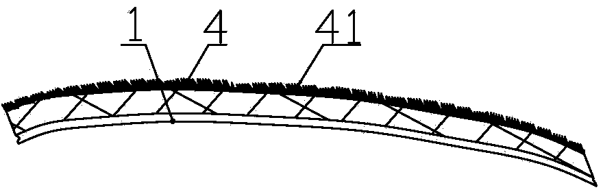
[0023] Such as figure 1 with image 3 As shown, the difference from the above-mentioned embodiment is that: on the basis of the above-mentioned embodiment, a brush-shaped sleeve 41 is fixedly arranged at the edge of the flexible rubber layer 4 , and the brush-shaped sleeve 41 is along the The entire edge of the flexible rubber layer 4 extends, and the peripheral edge of the brush-shaped sleeve 41 is in contact with the inner edge of the delivery tubular cavity 3 . The brush part of the brush-shaped sleeve 41 is made of wear-resistant material. This can not only prolong the use time of the non-destructive screw conveying device, but also the peripheral edge of the brush-shaped sleeve 41 contacts the inner edge of the conveying tubular cavity 3, which can realize complete conveying without damage and residue.


PUM


Abstract

A lossless spiral conveying device comprises more than one spiral vane for conveying, a rotating shaft, a conveying tubular cavity and a flexible rubber layer. The rotating shaft axially penetrates the conveying tubular cavity, and two ends of the rotating shaft are installed in bearing seats installed on a frame through bearings. The spiral vanes for conveying are spirally arranged on the outer wall of the rotating shaft located in the conveying tubular cavity. The flexible rubber layer is fixed on the edges of the spiral vanes for conveying in a detachable mode and extends along the spiral direction of the spiral vanes for conveying. Lossless conveying of crop grains is achieved by means of contact of the crop grains and the metal vanes for conveying. The conveying capability is obviously improved by means of the spiral conveying structure.

Description

technical field [0001] The invention relates to a conveying system of a harvester, in particular to a non-destructive screw conveying device. Background technique [0002] After the existing combine harvester has threshed crops such as corn, it needs to collect the corn grains in the grain collector, and then the grain collector is transported to the grain delivery device, and finally the grain delivery device transports the corn grains to the grain collection bin. The structure of the currently commonly used grain conveying devices is mostly scraper type or auger type, and the scraper or auger sheets involved in the two types of conveying devices are all made of metal materials and they are when the conveying is completed. direct contact with crop seeds. Because of the scraping action of the scraper or the high-speed agitation of the auger, the crop grains will inevitably be damaged during the transportation process, causing the skin of the crop grains to be broken or defo...

Claims


Application Information

Patent Timeline
Patent Type & Authority Applications(China)
IPC IPC(8): A01D41/12A01F12/46
Inventor 赵利文王彩华
Owner SHANDONG RUNYUAN IND
Why Eureka
Try Eureka