A mold for manufacturing cylindrical mirror array

A cylindrical mirror and array technology is applied in the field of molds for manufacturing cylindrical mirror arrays, which can solve the problems of many processing links, time-consuming and laborious, and high defective rate, and achieve the effect of reducing process links, reducing costs, and improving optical performance indicators.

Active Publication Date: 2016-11-30
NO 27 RES INST CHINA ELECTRONICS TECH GRP
View PDF3 Cites 0 Cited by
  • Summary
  • Abstract
  • Description
  • Claims
  • Application Information

AI Technical Summary

Problems solved by technology

[0005] 1) The process is complicated, there are many processing links, time-consuming and labor-intensive, and the cost is high
[0006] Glass cylindrical mirror arrays cannot be produced through moulds, and multiple cylindrical mirrors need to be processed and bonded separately. The main processes include cutting, rough grinding, fine grinding, polishing, precise measurement, bonding, etc., which is not conducive to mass production. Production, many process links cause high cost
[0007] 2) The bonding link is difficult to control and the defective rate is high
[0008] The cylindrical mirror array made of glass is composed of multiple single cylindrical mirrors bonded together. Before bonding, the single cylindrical mirrors need to be precisely measured, otherwise there will be defective products caused by insufficient processing precision of the single cylindrical mirrors; In the bonding process of the measured single cylindrical mirror, it is easy to have defective products caused by adhesive bubbles

Method used


Image

  • A mold for manufacturing cylindrical mirror array
  • A mold for manufacturing cylindrical mirror array
  • A mold for manufacturing cylindrical mirror array

Examples


Embodiment Construction

[0032] In order to further explain the technical means and functions adopted by the present invention to achieve the intended purpose, the present invention will be described in detail below in conjunction with the accompanying drawings and preferred embodiments.

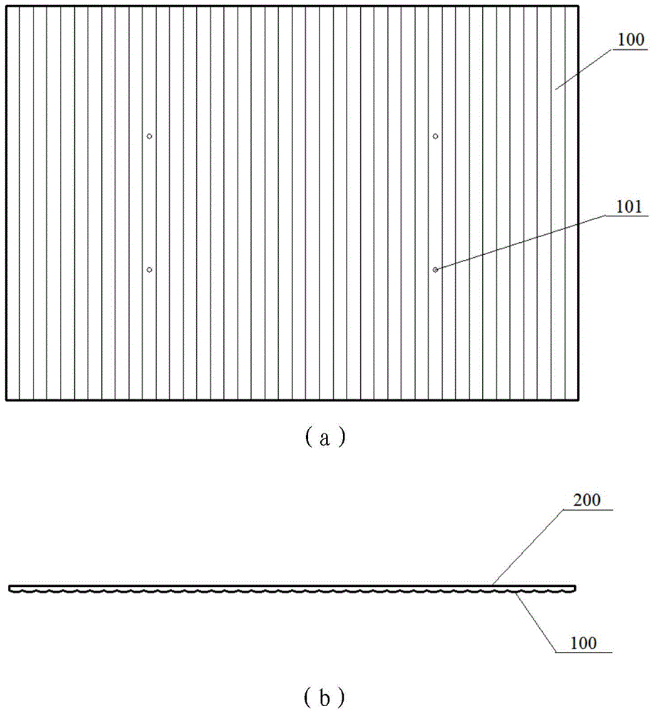
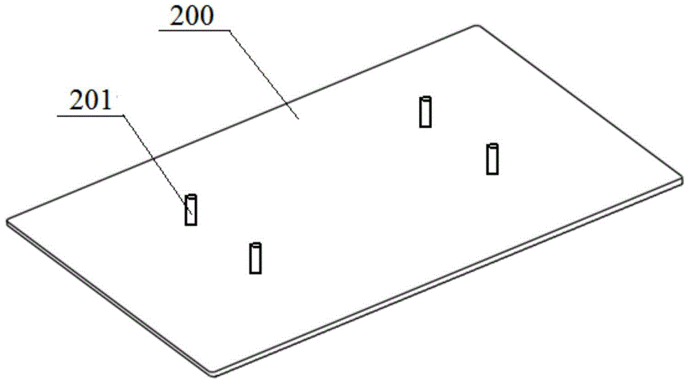
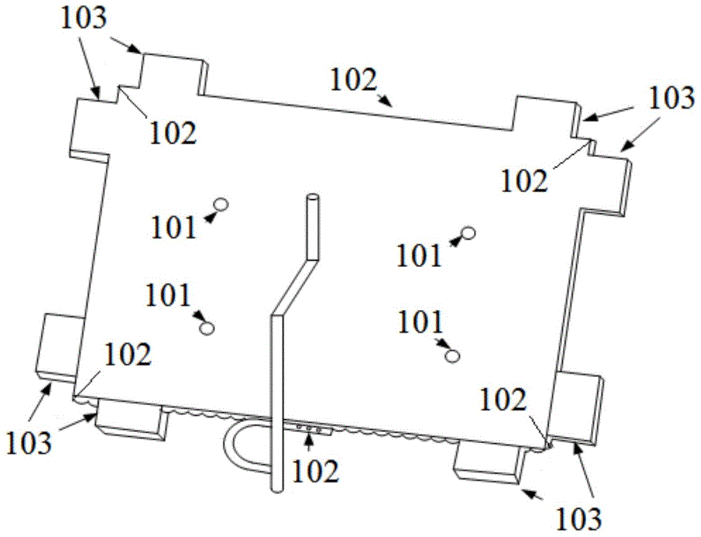
[0033] A mold for manufacturing a cylindrical mirror array according to an embodiment of the present invention, such as figure 1 As shown in (a) and (b), it includes the following components: a male mold assembly, a female mold assembly and a runner assembly, wherein the female mold assembly includes a box body 100, and the bottom surface of the box body 100 presents a cylindrical surface Mirror-shaped envelope, the male mold assembly includes a plane plate 200 as the upper cover plate of the box body, the plane plate is matched with the box body and tightly bonded at the edge. The flow channel assembly is connected to one side of the box body 100, and raw materials are injected into the box body through the flow ch...


PUM

PropertyMeasurementUnit
thicknessaaaaaaaaaa
radiusaaaaaaaaaa

Abstract

The present invention provides a mold for manufacturing a cylindrical lens array, comprising: a male mold assembly, a female mold assembly and a runner assembly, wherein the female mold assembly includes a box body, and the bottom surface of the box body presents Out of the envelope in the shape of a cylindrical mirror, the male mold assembly includes a flat plate as the upper cover plate of the box body, the flat plate is matched with the box body and is tightly combined at the edge; the flow channel assembly is One side of the box body is connected, and the raw material is injected into the box body through the flow channel assembly. The mold for manufacturing the cylindrical lens array of the present invention is used when high-light-transmitting PC material or PMMA material is used instead of glass material to manufacture the cylindrical lens array, which can reduce the process links of cylindrical lens processing and achieve better optical quality. Performance indicators, reduce costs, suitable for mass production.

Description

technical field [0001] The invention relates to the technical field of PTN networks, in particular to a mold for manufacturing cylindrical mirror arrays. Background technique [0002] In optical system design, aspheric optical parts can obtain better imaging quality than spherical optical parts. At the same time, using one or several aspheric parts instead of multiple spherical parts can simplify the component structure in the optical system. , effectively reduce the quality of components, and correct a variety of imaging deviations, improve imaging quality, and improve the performance of the optical system. [0003] Cylindrical lens is a common aspheric optical element. Its main function is that when a parallel light beam passes through the cylindrical lens, it can make the focal point be drawn into a line along one direction. It is widely used in various optical systems; it is composed of multiple The form of cylindrical mirrors forming an array is also widely used. Becau...

Claims


Application Information

Patent Timeline
Patent Type & Authority Patents(China)
IPC IPC(8): B29C45/26B29C45/27B29C45/73
Inventor 周军华李卫森姚永庆范海震韩树科雷飚
Owner NO 27 RES INST CHINA ELECTRONICS TECH GRP
Why Eureka
Try Eureka