

A rolling contact pantograph head
A rolling contact, pantograph technology, applied in the direction of collectors, electric vehicles, power collectors, etc., can solve the problem of shortening the service life of sliding contact pantograph slides and catenary wires, and the use of pantograph slides and catenary wires. Short life, friction and wear between pantograph sliding plate and catenary wires, etc., to achieve the effect of maintaining safe and stable operation, reducing maintenance workload and simple structure
- Summary
- Abstract
- Description
- Claims
- Application Information
AI Technical Summary
Problems solved by technology
Method used
Image

Examples
Embodiment Construction
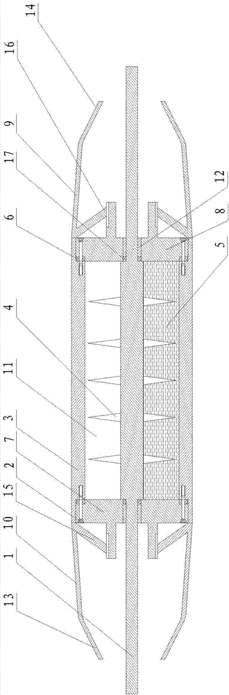
[0021] The present invention will be further described in detail below in conjunction with the accompanying drawings and specific embodiments.
[0022] Such as figure 1 As shown, a rolling contact pantograph head includes a roller 3, left and right end caps with through holes, conductive vanes 4, conductive liquid 5, metal conductive shaft 1 and left and right lead angles; the roller 3 is through Cylindrical structure, the main function is to produce rolling contact with the catenary wire, reduce friction and wear and conduct current; the metal conductive shaft 1 is set in the drum 3, and the left and right end covers are respectively set at the left and right ends of the drum 3 The two ends of the metal conductive shaft 1 pass through the through holes of the left and right end caps respectively, and are arranged outside the space formed by the left and right end caps and the drum 3. The metal conductive shaft 1, the left and right end caps and the drum 3 form a closed inner ...
PUM
 Abstract
Description
Claims
Application Information