
High-frequency annealing device of semi-automatic bearing

A high-frequency annealing, semi-automatic technology, applied in the field of bearing processing, can solve the problems of large randomness, difficult quality assurance, insufficient channel hardness, etc., and achieve the effects of good stability, improved processing quality, and uniform annealing.

Active Publication Date: 2014-04-23
ZHEJIANG XCC GRP CO LTD
View PDF7 Cites 13 Cited by
  • Summary
  • Abstract
  • Description
  • Claims
  • Application Information

AI Technical Summary

Problems solved by technology

[0002] In the outer spherical bearing, the annealing of the screw hole of the inner ring is a very critical process, because the annealing quality of the screw hole of the inner ring is not good (1, secondary quenching occurs near the screw hole; 2, the hardness near the screw hole has not retreated; 3, the groove The hardness of the channel is not enough;) the inner ring is broken or the service life is reduced due to the hardness of the channel.
At present, the annealing equipment on the market is high-frequency power supply + simple chuck (positioning inner ring) + annealing coil. Such processing equipment is all manually operated, and the randomness is relatively large, and the quality is difficult to guarantee. The quality stability of a batch of products is processed Not good, it is difficult to guarantee high-quality bearings, which affects the overall quality of the bearings

Method used


Image

  • High-frequency annealing device of semi-automatic bearing
  • High-frequency annealing device of semi-automatic bearing
  • High-frequency annealing device of semi-automatic bearing

Examples


Embodiment Construction

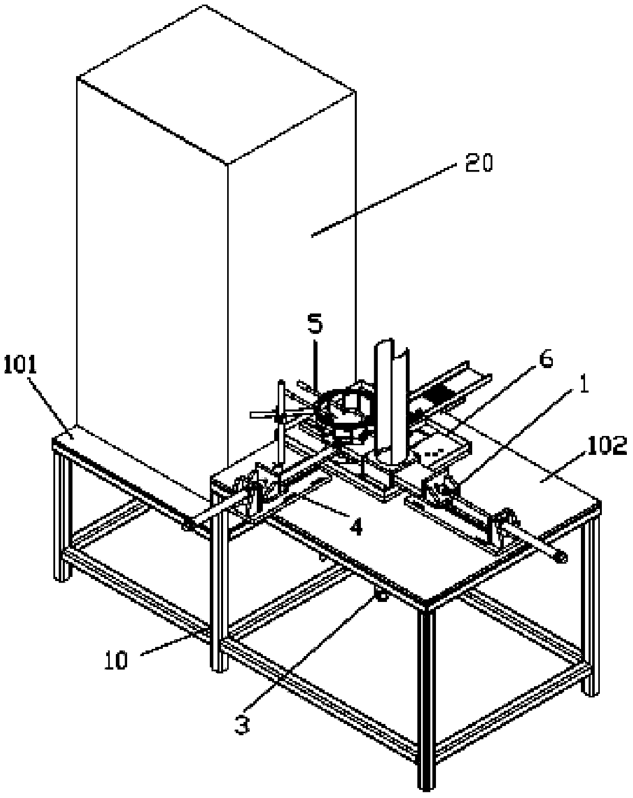
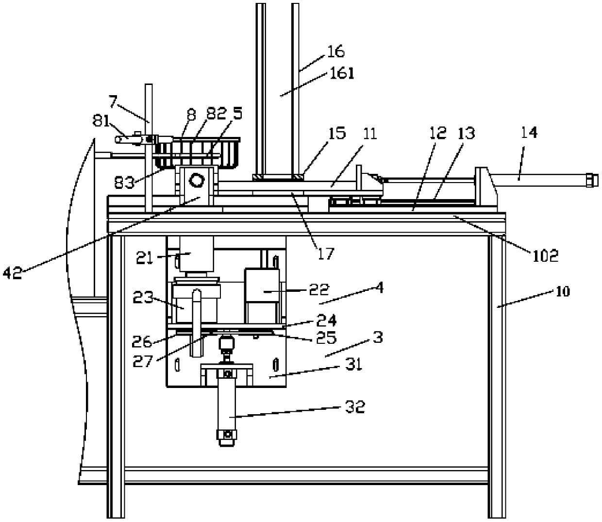
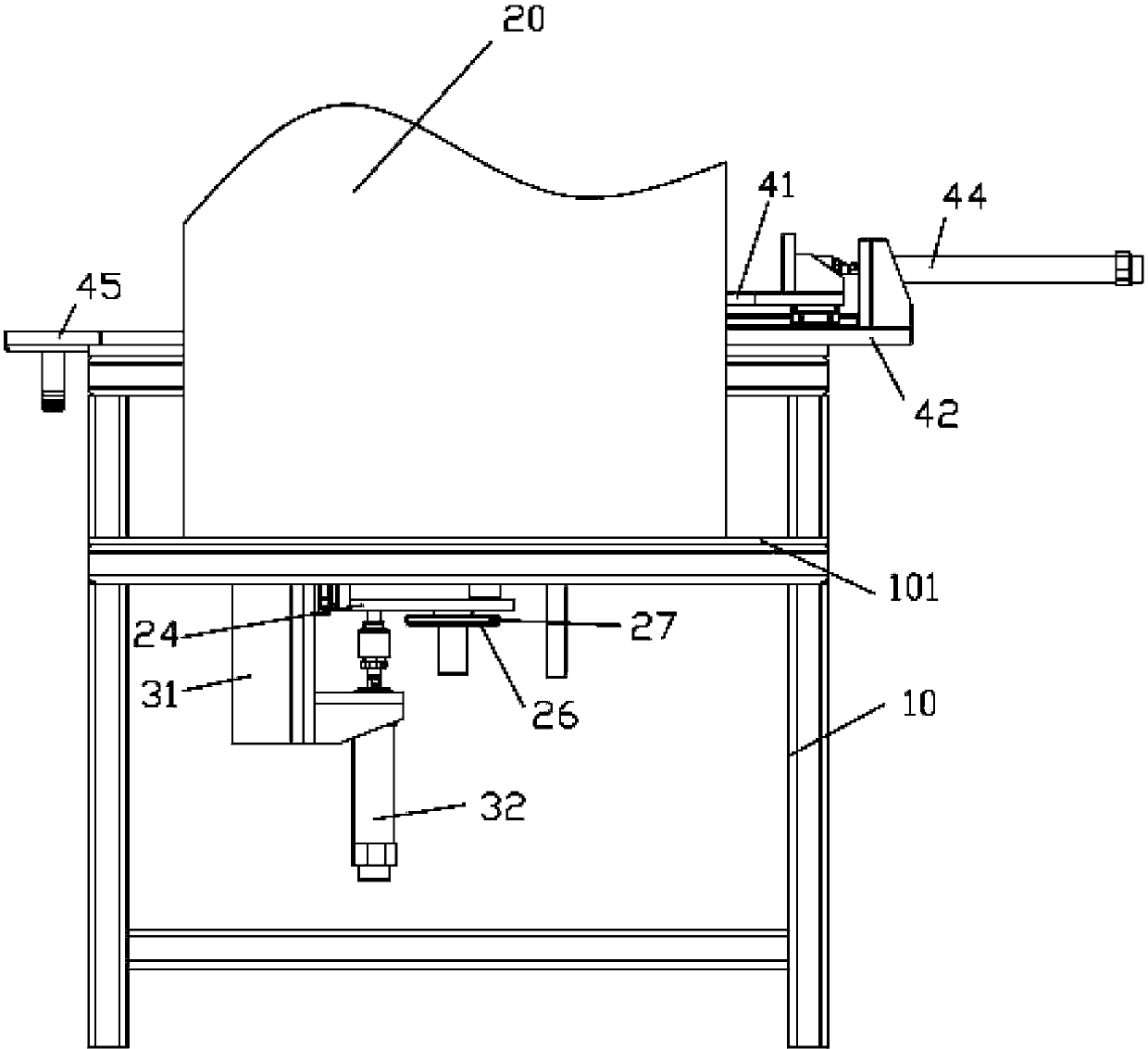
[0026] Examples, see e.g. Figures 1 to 8 As shown, a semi-automatic bearing high-frequency annealing device includes a frame 10 and a high-frequency power supply device 20. The high-frequency power supply device 20 is fixed on the left support plate 101 of the frame 10, and the right side of the frame 10 supports The plate 102 is fixed with a feeding device 1, a rotating device 2, a lifting device 3 and a material return device 4, the lifting device 3 is fixed on the back side of the right support plate 102 of the frame 10, and the push rod of the lifting device 3 is fixed with a rotating Device 2, the rotating shaft 21 of the rotating device 2 is inserted into the circular through hole 103 formed on the right support plate 102, and the induction coil 5 is installed on the high frequency power supply device 20, and the induction coil 5 is mounted on the right support plate 102 above, its central axis is the same axis as the central axis of the rotating shaft 21, the feeding d...


PUM


Abstract

The invention discloses a high-frequency annealing device of a semi-automatic bearing. The high-frequency annealing device comprises a machine frame and a high-frequency power supply device, wherein the high-frequency power supply device is fixed on a left-side supporting plate of the machine frame; a feeding device, a rotating device, a lifting device and a discharging device are fixed on the right-side supporting plate of the machine frame, the lifting device is fixed on the reverse side of the right-side supporting plate of the machine frame, the rotating device is fixed on a push rod of the lifting device, and a rotating shaft of the rotating device is inserted and sleeved in a circular through hole formed in the right-side supporting plate; an induction coil is mounted on the high-frequency power supply device, and is above the right-side supporting plate, and the induction coil and the rotating shaft share the same central axis; the feeding device and the discharging device are fixed on the upper plane of the right-side supporting plate, a feed end of a feed plate of the feeding device faces to the circular through hole, and a discharging end of a discharging plate of the discharging device faces to the circular through hole. The high-frequency annealing device can automatically feed to anneal, the hardness of the inner ring of the bearing is ensured, annealing is even, the secondary quenching phenomenon is not generated, the processing quality is increased, and the stability is good.

Description

Technical field: [0001] The invention relates to the technical field of bearing processing, in particular to a semi-automatic bearing high-frequency annealing device. Background technique: [0002] In the outer spherical bearing, the annealing of the screw hole of the inner ring is a very critical process, because the annealing quality of the screw hole of the inner ring is not good (1, secondary quenching occurs near the screw hole; 2, the hardness near the screw hole has not retreated; 3, the groove The channel hardness is not enough;) the inner ring is broken or the service life is reduced due to the channel hardness is not enough, which causes the main engine to malfunction and leads to the paralysis of the entire production line. At present, the annealing equipment on the market is high-frequency power supply + simple chuck (positioning inner ring) + annealing coil. Such processing equipment is all manually operated, and the randomness is relatively large, and the quali...

Claims


Application Information

Patent Timeline
IPC IPC(8): C21D9/40
Inventor 石勇汪凯徐庆发王一斌王红英尚延伟
Owner ZHEJIANG XCC GRP CO LTD
Learn More