A Double Shear Plate Transfer Beam-Column Joint

A beam-column joint and conversion beam technology, which is applied to buildings and building structures, can solve problems such as increased construction costs, waste of structural steel bars, and increased stress-bearing steel bars for frame-supported beams. The effect of improving the shear capacity

Active Publication Date: 2016-09-14
广东省建科建筑设计院有限公司
View PDF5 Cites 0 Cited by
  • Summary
  • Abstract
  • Description
  • Claims
  • Application Information

AI Technical Summary

Problems solved by technology

[0005] (1) Increasing the beam section will reduce the headroom of the large space at the bottom, which will affect the use of building functions, and the self-weight will increase, the absorbed seismic force will increase, and the seismic effect will be large. In addition, for some frame beams, the reinforced steel bars at the end tend to be For structural reinforcement, increasing the beam section will undoubtedly increase the stress reinforcement of the frame support beam, resulting in waste of structural reinforcement and increasing construction costs
[0006] ⑵Using high-grade concrete grades for construction, because it is difficult to achieve high-grade concrete grades during actual construction, the construction quality is difficult to guarantee
[0007] (3) Steel concrete beams are used, the construction process is relatively complicated, the construction period is long, and the professional requirements of the construction team are relatively high

Method used


Image

  • A Double Shear Plate Transfer Beam-Column Joint
  • A Double Shear Plate Transfer Beam-Column Joint
  • A Double Shear Plate Transfer Beam-Column Joint

Examples


Embodiment 1

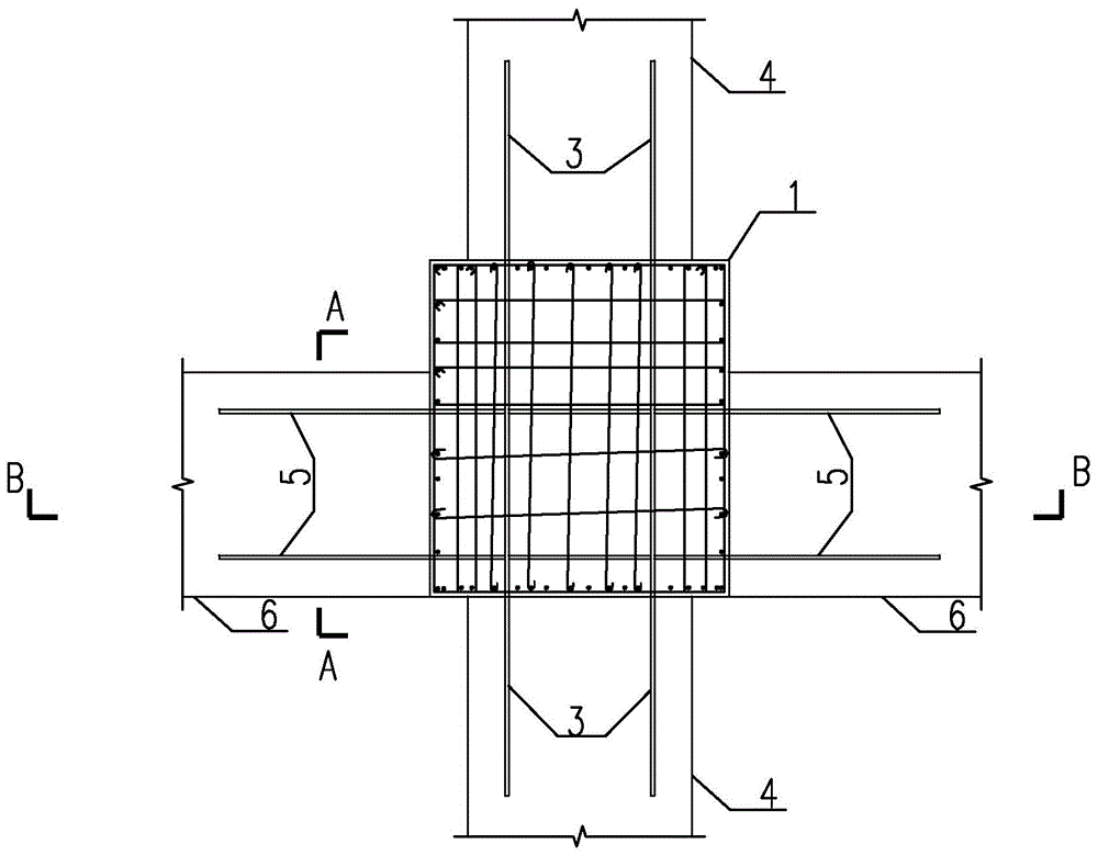
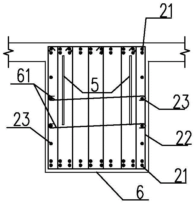
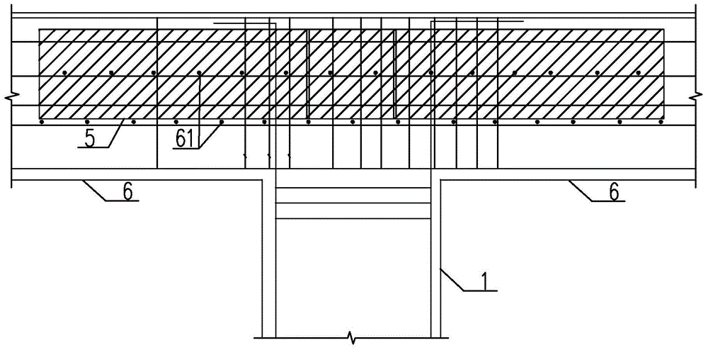
[0033] Such as Figure 1~3 As shown, a double shear plate transfer beam-column node of the present invention includes a transfer column 1 and a concrete transfer beam, the concrete transfer beam is composed of concrete and steel bars, and the steel bars include longitudinal bars 21, stirrups 22 and waist bars 23, and each A pair of parallel shear steel plates are vertically arranged in the beam end of a concrete transfer beam along its length direction, the thickness of the shear steel plates is 6-30 mm, and the distance between the shear steel plates and the beam side of the concrete transfer beam is at least 120 mm, The distance between the top surface of the shear steel plate and the beam top of the concrete transfer beam is at least 100mm, which can meet the minimum protective layer thickness requirements. The specific values ​​of the length, height and thickness of the shear steel plate can be calculated according to the comprehensive shear envelope diagram of the structur...

Embodiment 2

[0036] The difference between this embodiment and Embodiment 1 is that the concrete transfer column and the concrete transfer beam intersect in an "L" shape, and there are two pairs of shear steel plates, of which one pair of shear steel plates is located in one of the concrete as the first shear steel plate. In the transfer beam, another shear steel plate is located in another concrete transfer beam as the second shear steel plate, and the second shear steel plate is cut by the first shear steel plate at the beam-column connection.

Embodiment 3

[0038] Such as Figure 4 As shown, the difference between this embodiment and Embodiment 1 is that the transfer column 1 is a steel-concrete transfer column, the steel frame of the steel-concrete transfer column is cross-shaped steel, and the steel-concrete transfer column intersects with the concrete transfer beam in the shape of a "cross" , there are two pairs of shear steel plates, one of which is located in a pair of opposite concrete transfer beams 8 as the first shear steel plate 7, and the pair of first shear steel plates 7 are respectively connected to a pair of flanges of cross-shaped steel butt joint, the flange is the first flange 12, and the other shear steel plate is located in another pair of opposite concrete transfer beams 10 as the second shear steel plate 9, and is cut by the first shear steel plate 7, one of which The second shear steel plate 9 is docked with one of the other pair of flanges 13 of the cross-shaped steel, and another second shear steel plate ...


PUM


Abstract

The invention discloses a double shearing resistant plate transformation beam-column joint which comprises transformation column and concrete transformation beams. A pair of parallel shearing resistant steel plates are vertically arranged at the beam end of each concrete transformation beam along the length direction of the concrete transformation beam and mutually connected at the beam-column joint of the concrete transformation beam and the corresponding transformation column in a penetrating manner. The shearing resistant steel plates are additionally arranged at the ends of the concrete transformation beams, the shearing capacity of the sections of the transformation beams is improved, and requirements of the shear-compression ratio stipulated by specifications are met. Compared with conventional methods such as enlarging beam sections and concrete strength or using profile steel concrete sections, the use ratio of building space can be increased, structural weight is reduced, earthquake effect is decreased, construction cost is reduced, construction is simple, construction quality is ensured, and construction period cannot be affected.

Description

technical field [0001] The invention relates to the field of construction engineering, in particular to a transfer beam-column joint with double shear slabs, which is used in a transfer structure, and is especially suitable for a transfer structure in which a shear wall is arranged on the transfer beam. Background technique [0002] In recent years, with the rapid development of high-rise buildings, buildings are developing in a comprehensive direction with complex shapes and diverse functions, so the corresponding structural forms of high-rise buildings are also complex and diverse. This often requires that the upper floors of the building be arranged with residences and hotels in terms of use function, the middle floors be used as office rooms, and the lower floors are used as shops, restaurants and cultural and entertainment facilities. Floors with different uses require bays of different sizes and adopt different structural forms. Specifically, the building requires mor...

Claims


Application Information

Patent Timeline
Patent Type & Authority Patents(China)
IPC IPC(8): E04B1/58
Inventor 陈林李俞谕许燕禄刘春艳邓建强
Owner 广东省建科建筑设计院有限公司
Why Eureka
Try Eureka