Bilateral guide vane through-flow turbine with elliptical runners

A tubular turbine and elliptical technology, applied in the field of double-sided guide vane tubular turbines, can solve the problems of complex three-dimensional simulation modeling and manufacturing process, poor hydraulic performance of reverse power generation, and reduced forward power generation efficiency, etc. Achieve the effect of improving reverse power generation efficiency, improving power generation efficiency, and large overflow

Active Publication Date: 2014-04-23
HOHAI UNIV +1
View PDF8 Cites 16 Cited by
  • Summary
  • Abstract
  • Description
  • Claims
  • Application Information

AI Technical Summary

Problems solved by technology

However, the channel of the device adopts a rectangular section, and the transition from the inlet section to the guide vane inlet section is a square circle, which is complicated in the three-dimensional simulation modeling and manufacturing process, and the actual application effect is not good.
At present, most of the two-way tidal power plants adopt the structure of one-sided guide vane. When the single-side movable guide vane is used, the hydraulic performance of forward power generation can be improved by adjusting the matching angle between the movable guide vane and the blade. In reverse power generation, there is no rear movable guide vane, and the water flow does not form a certain circulation before entering the runner, which cannot cooperate well with the blades, resulting in poor hydraulic performance of reverse power generation
[0005]The paper published by Yang Chunxia "Bidirectional Power Performance of a Tidal Unit with

Method used


Image

  • Bilateral guide vane through-flow turbine with elliptical runners
  • Bilateral guide vane through-flow turbine with elliptical runners
  • Bilateral guide vane through-flow turbine with elliptical runners

Examples


Embodiment Construction

[0023] The specific implementation manners of the present invention will be further described in detail below in conjunction with the accompanying drawings.

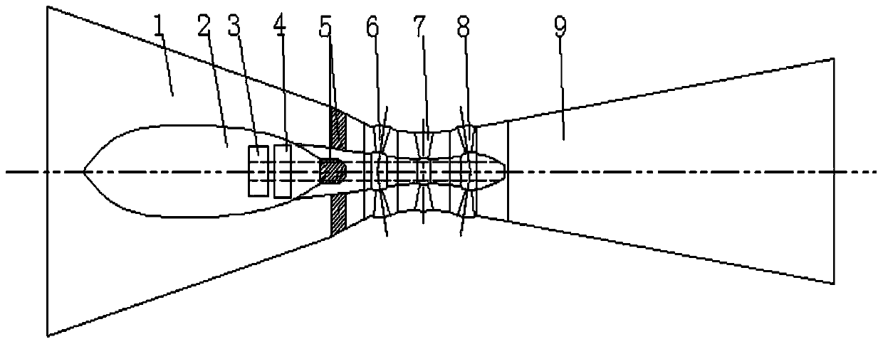
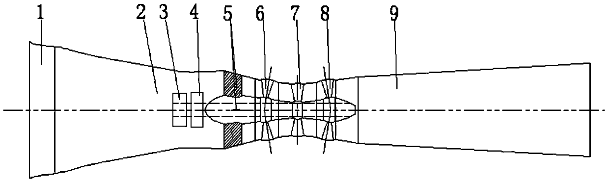
[0024] combine figure 1 and figure 2 , the present invention proposes a double-side guide vane tubular water turbine with an elliptical flow channel, which includes a forward water inlet channel (1), a shaft (2), a support frame (5), and forward movable guide vanes (6), two-way power generation runner (7), reverse movable guide vane (8), reverse water inlet flow channel (9), generator (3) and speed increaser (4), the generator (3) It is connected with the two-way power generation runner (7) through the speed increaser (4); the generator (3) and the speed increaser (4) are placed in the shaft (2); the forward movable guide vane (6) is arranged in the forward direction Between the water channel (1) and the two-way power generation runner (7); the reverse movable guide vane (8) is set between the two-way power generation...


PUM


Abstract

The invention relates to a bilateral guide vane through-flow turbine with elliptical runners. The bilateral guide vane through-flow turbine comprises a forward inflow runner, a vertical shaft, a supporting frame, a forward movable guide vane, a bidirectional power generation rotating wheel, a reverse movable guide vane, a reverse inflow runner, a generator and a speed increaser. The bilateral guide vane through-flow turbine is characterized in that the forward inflow runner has a forward elliptical section, the ratio of the short axis to the long axis of the forward inflow runner is a golden division ratio, the ratio of the short axis to the long axis of an ellipse from a forward inflow section to an inflow section in front of a forward movable guide vane section is linearly and gradually increased, the reverse inflow runner has a reverse elliptical section, the ratio of the short axis to the long axis of the reverse inflow runner is a golden division ratio, and the ratio of the short axis to the long axis of an ellipse from a reverse inflow section to an inflow section in front of a reverse movable guide vane section is linearly and gradually increased. By the aid of the bilateral guide vane through-flow turbine, water flow can smoothly and symmetrically flow in the elliptical runners, the overall power generation efficiency of a generator set is further improved, and the bilateral guide vane through-flow turbine is applicable to various vertical shaft through-flow turbines of low-head tidal power stations.

Description

technical field [0001] The invention belongs to the technical field of fluid machinery and hydropower engineering equipment, in particular to a double-side guide vane tubular water turbine provided with an elliptical flow channel. [0002] Background technique [0003] With the large-scale development of my country's hydropower resources, there are fewer and fewer medium and high head sites with good economic indicators, and the development of low head runoff power stations, especially the development and utilization of tidal energy, has become a research hotspot and has entered practical use. sexual stage. The known tubular turbine has become the most economical and suitable turbine type in the development of low-head hydropower resources because of its large flow rate, high speed and high efficiency, wide high-efficiency zone, compact structure and simple layout. How to use these advantages to develop a high-efficiency low-head, high-flow two-way shaft tubular unit that c...

Claims


Application Information

Patent Timeline
IPC IPC(8): F03B13/00F03B3/18
CPCY02E10/223Y02E10/20
Inventor 张玉全郑源杨春霞阚阚刘惠文姜镐
Owner HOHAI UNIV
Why Eureka
Try Eureka