
A phase-adjustable elastic shaft load sharing device

A technology of elastic shaft and phase, which is applied in the direction of transmission, transmission parts, gear transmission, etc., can solve the problems of increasing the number of transmission system parts, reducing system reliability, and many components

Active Publication Date: 2016-08-17
NORTHWESTERN POLYTECHNICAL UNIV
View PDF8 Cites 0 Cited by
  • Summary
  • Abstract
  • Description
  • Claims
  • Application Information

AI Technical Summary

Problems solved by technology

Both of the above two structures use the flexible shaft to produce different torsional deformations on the two branches to achieve load sharing. The connection method of the flexible shaft of the two structures is more complicated, with more components, and at the same time increases the axial size of the system.
[0004] In the invention patent CN201547185U, an "automatic load-sharing power split gear device" is described. In the power split gear device, it is pointed out that the torque shaft used in the power four-branch gear transmission system sometimes cannot meet the load sharing requirements. Add radial stop rings to improve load sharing performance
It can be seen that the load sharing is achieved through the torsional deformation of the shaft, which cannot meet the high load sharing requirements
Adding a limit ring increases the drivetrain part count, making the system less reliable, while increasing the size and weight of the system

Method used


Image

  • A phase-adjustable elastic shaft load sharing device
  • A phase-adjustable elastic shaft load sharing device
  • A phase-adjustable elastic shaft load sharing device

Examples


Embodiment Construction

[0018] This embodiment is a phase-adjustable elastic shaft load sharing device.

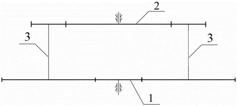
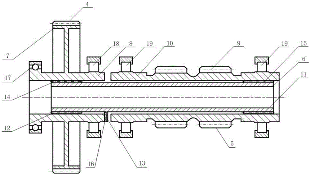
[0019] refer to figure 1 , figure 2 , a power splitting gear transmission system of a certain type is composed of input small spur gear 1, output large herringbone gear 2 and two elastic shaft equalizing devices 3; two elastic shaft equalizing devices 3 divide the power splitting gear transmission system into left and right Two branches, the left branch includes input small spur gear 1, output large herringbone gear 2 and left elastic shaft load sharing device 3; the right branch includes input small spur gear 1, output large herringbone gear 2 and right elastic shaft Shaft load sharing device 3. The input small spur gear 1 meshes with the large spur gear 7 of the left elastic shaft equalizing device 3 and the large spur gear 7 of the right elastic shaft equalizing device 3; the small herringbone gear of the left elastic shaft equalizing device 3 9 and the small herringbone gear 9 of the elas...


PUM


Abstract

The invention discloses an elastic shaft uniform load device with adjustable phase positions. The elastic shaft uniform load device with the adjustable phase positions comprises an input mechanism, an output mechanism and an elastic shaft, a large straight gear and a large straight gear shaft of the input mechanism are integrated, and a second helical tooth spline arranged in an inner hole in the large straight gear shaft is connected with a first straight tooth spline arranged at the end of the elastic shaft. Small zig-zag gears and a small zig-zag gear shaft of the output mechanism are integrated, a second straight tooth spline arranged in a through hole in the small zig-zag gear shaft is connected with the first straight tooth spline of the elastic shaft, gaskets are located between shaft shoulders of the elastic shaft and ends of the large straight gear shaft, the thickness of the gaskets is adjusted to enable the elastic shaft to axially move so that the input mechanism can twist at a certain angle in a peripheral direction, the output mechanism can not twist in the peripheral direction, and the phase positions between the large straight gear of the input mechanism and the small zig-zag gears of the output mechanism can be changed. The elastic shaft uniform load device with the adjustable phase positions is simple in structure, the phase positions of elastic shaft uniform load devices are adjusted to change uniform load performances of a power dividing gear driving system, and high uniform load requirements can be met.

Description

technical field [0001] The invention belongs to the field of gear transmission, and in particular relates to a phase-adjustable elastic shaft load sharing device; it is especially suitable for a power split gear transmission system. Background technique [0002] At present, the power split gear transmission system has been widely used in the fields of aviation, ships, weapons and heavy machinery. For the power split gear transmission system, there is a situation where one gear meshes with multiple gears at the same time. Due to the errors in manufacturing and installation, the load of each branch of this transmission system cannot be evenly distributed. The no-load phenomenon will seriously affect the strength and fatigue life of the system. Therefore, its load-sharing characteristics have always been the focus of attention. [0003] Chinese patent CN201636273U discloses a "power double-split central drive mill reducer load sharing structure", which uses a flexible shaft t...

Claims


Application Information

Patent Timeline
Patent Type & Authority Patents(China)
IPC IPC(8): F16H1/20
CPCF16H1/20F16H57/022F16H57/023F16H2057/0221
Inventor 付晨曦赵宁赵永志宋阿娟扶碧波
Owner NORTHWESTERN POLYTECHNICAL UNIV
Learn More